What does this mean? It is the spacing of the frequency domain data points.
It is also the lowest frequency that the filter can influence. In actuality, the realized resolution is a bit lower (higher in frequency) since a few periods of the waveform are required to determine frequency.
What would happen if we add more taps? Doubling the filter length will double the frequency resolution, making the frequency spacing of the data points 24 Hz.
It will also reduce the LF limit of the filter by one-half, to about 24 Hz. This trend continues. Each doubling of the number of taps extends the filter’s response downward by one octave. So, longer FIRs allow:
1) The filtering to extend to a lower frequency.
2) Higher detail in the frequency response of the filter, since the data points are closer together.
The minimum phase FIR is a case where more taps could be beneficial, since more taps means that the filter can extend lower in frequency. Since the filter is minimum phase, there is no additional processing delay over an IIR filter. About 4096 taps would be required to flatten my example file. This is far more taps than supported by any current DSP, and it fuels the argument that more taps are needed.
But Wait, There’s More…
Here’s the pushback. A minimum phase FIR behaves just like a minimum phase IIR filter, but requires a sufficient number of taps to affect the lowest frequency of interest. Low frequency equalization requires long filter lengths.
But why use a processor-hungry FIR filter block in your DSP to apply a min phase filter? A properly tuned parametric EQ block (IIR) will produce the same response with better frequency resolution using far fewer system resources (Figure 7). It’s good audio practice to achieve the needed result using as few system resources as possible, and using FIRs for minimum phase equalization is not efficient.
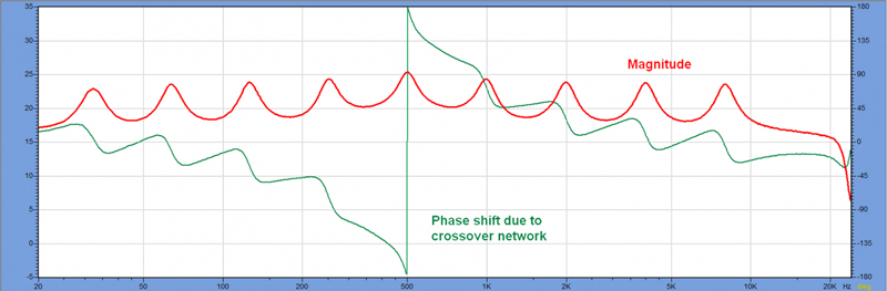
Let’s next consider a case where the response being corrected is non-minimum phase. I took my reference file and added a second order all pass filter (500 Hz) to the response (Figure 8). This causes a phase shift over the bandwidth of the filter, with minimal effect on the magnitude response. In real life, this all pass behavior can result from the use of a crossover network. A minimum phase FIR cannot compensate for this additional phase shift.
Linear Phase To The Rescue!
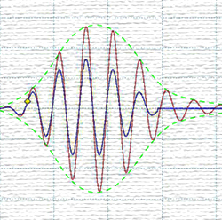
A linear phase FIR has a two-sided impulse response, where the main signal arrival is centered in the IR (Figure 9). Let’s make the arrival peak relative time zero. The time span preceding the main arrival provides a place for the “negative time” arrivals necessary to conjugate energy arrivals after the main arrival peak.
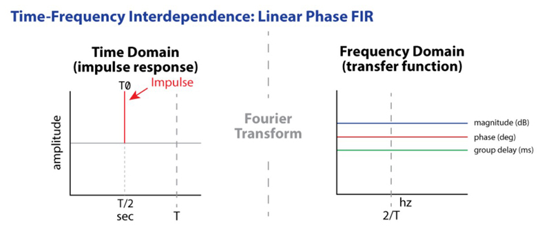
These “pre-delays” are causal in respect to real time, but acausal with respect to the main signal arrival. This allows the filter to compensate for reflections using an opposite “negative time” response.
So, if your tap length is 1024 points, a linear phase FIR will place the main arrival at T/2, allowing one-half the filter length to provide the pre-arrivals necessary to conjugate the post arrivals produced in the loudspeaker or room. It also allows the introduction of the negative group delay necessary to compensate for the all pass response of the crossover.
By using one-half (1/2) of the filter length for “negative relative time” corrections, the frequency resolution of the filter is halved. For example, a 1024 tap min phase FIR has 47.6 Hz frequency resolution. The same tap length for a linear phase FIR has a frequency resolution of 95.2 Hz, since up to one-half of the filter length is reserved for phase equalization.
Are More Taps Better?
As with the minimum phase FIR, it would seem so. The pushback here is that one-half of the filter length is preserved for non-minimum phase equalization. This translates into processing delay (often incorrectly referred to as latency). Unlike the minimum phase FIR, the delay of a linear phase FIR increases as it is lengthened to increase its frequency resolution. This is not due to the speed of the DSP. It results from TF = 1. There is just no escaping that relationship.
Let’s bring up my reference scenario again, but this time for a series of cut filters at the same frequencies as the original boost filters (Figure 10). From earlier, the group delay plot (blue trace) shows the time span of the filter ringing. Note that it appears to be negative, but that just means that the phase shift produced by the filter is increasing over the filter’s bandwidth. It does not mean that a “time advance” has occurred or that the filter’s response is acausal.
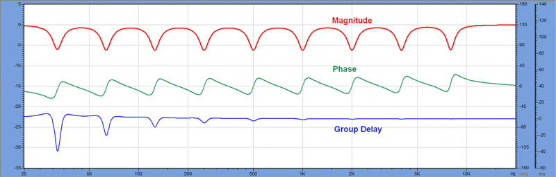
There is no getting around the fact that the time span that the filter must influence increases with decreasing frequency, and becomes very long (~40 ms) at the lowest octave center (31.5 Hz). For live sound and many installed sound applications, the long processing delay is unacceptable. A 1024 tap FIR (48 kHz sample rate) has a time span of 21 ms, which means that the processing delay is about 10.5 ms.
Increasing the sample rate to 96 kHz does not reduce the processing delay since twice the number of samples must be processed. There’s simply no getting around the fact that 21 ms of time only allows equalization down to about 48 Hz, with a realized frequency resolution of about 3 times 48 Hz or 150 Hz.
It Gets Worse
There is another drawback to linear phase FIR filters. Since “relative time zero” is centered in the filter’s time span, the frequency resolution is one-half that of a minimum phase FIR.