
Measurement Room
While it would be very nice to have an anechoic or hemi-anechoic chamber for loudspeaker measurements, they can be quite expensive to construct. An alternative is to measure in a very large, empty space and use an impulse response (IR) window to eliminate the reflections from the walls and ceiling.

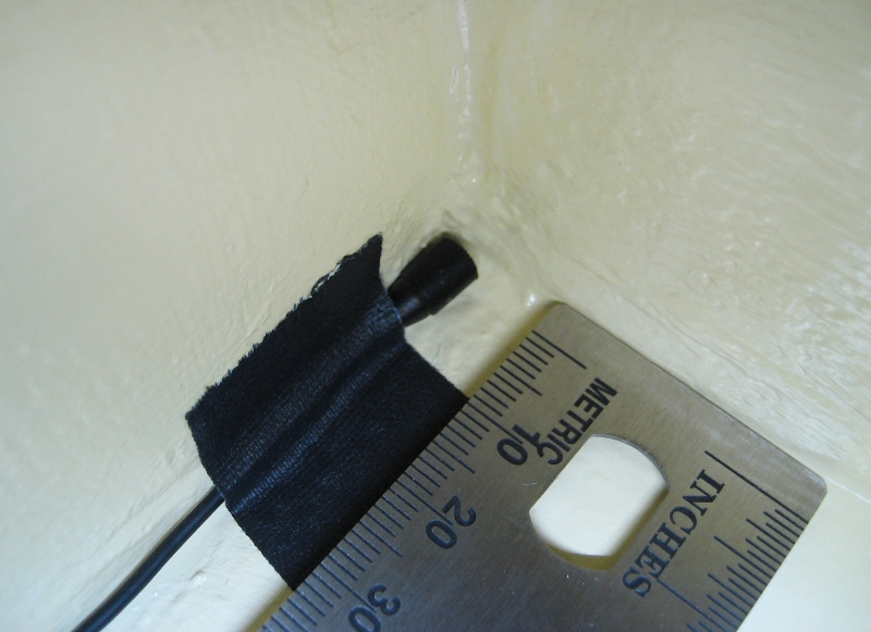
Typically this would require using a ground-plane measurement technique to eliminate the detrimental effects of the floor reflection. The use of the ground-plane technique can be expanded from a single boundary (floor) to three boundaries, the floor and the two adjacent walls. Placing the measurement mic in the corner of these three boundaries accomplishes this (Figures 2 and 3).
“Care must also be taken to use a mic that’s physically small,” Hughes says. “If it’s too large, the size can adversely affect the measurement data. As a result, a typical 1/2-inch or 1/4-inch measurement mic capsule is not suitable for this application.”
This trihedral (corner) measurement configuration can effectively eliminate the unwanted artifacts of reflections from three of a room’s surfaces. As a result, a smaller measurement space can be used to achieve similar results as measuring in the middle of a larger room.
All three of the surfaces forming the corner in which the measurement mic is placed must be acoustically reflective for all frequencies of interest, and they also need to be sufficiently rigid to not move or vibrate at low and midrange frequencies. Further, they must also be smooth and non-porous so that they do not absorb energy at high frequencies.
Hughes notes that Excelsior Audio was fortunate with its facility, in that the floor is smooth concrete that’s been sealed and painted. “This yields very good acoustic reflectivity to very high frequencies,” he says. “One wall (exterior) is reinforced masonry block that has been painted, which is a good starting point, but the rough texture of the block, even though it’s painted, can be problematic. We applied filler material to smooth a large area of this wall, near the corner, resulting in an appropriate surface.”
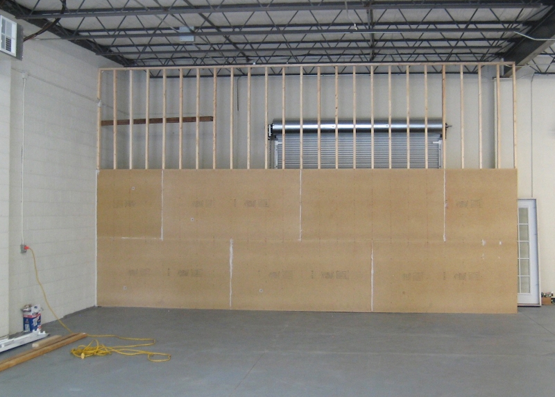
In addition, a new wall was built to form the third boundary (Figure 4). Typical construction techniques weren’t sufficient to produce the required rigidity, with reduced center-to-center stud spacing, multiple layers of MDF (medium density fiberboard), lots of screws (not nails), and construction adhesive helping to insure the requirements were met. (“Yes, the construction crew did think I was crazy,” Hughes adds with a laugh.)
While the reflections from three of the room surfaces are no longer a problem, the reflection from the ceiling can be. The space has a ceiling height of about 15 feet, and at a measurement distance of about 20 feet, the reflection from the ceiling would arrive at the measurement microphone only about 14 milliseconds (ms) after the direct sound. Using an IR window this short would limit the low-frequency accuracy and resolution of the resulting data to about 100 Hz.
To address the issue, fiberglass wedges were designed and constructed to be suspended from the ceiling. They measure 4.5 feet deep with an air space of about 1 foot behind them (Figure 5), resulting in very good absorption down to frequencies lower than the resolution limitations imposed by the IR window, and eliminates the effects of the first reflection (more on this later).