Exploring Arcs
From the explanation earlier in this article, we can guess that an electronic arc (where input signal is increasingly delayed as one goes from the center to the edges of the array) will display identical front and rear radiation for omnidirectional sources.
A physical arc, in the far field, also provides symmetrical front and rear behavior – but – at close distances, rear levels will be higher.
This is because circular arc sources arrive simultaneously at the circle’s center, i.e. the array’s “virtual origin.” Accordingly, physical arc best practices should avoid any arc that displays an inconvenient center, particularly at center stage.
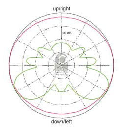
Figure 5a, 5b and 5c present polars for a physical arc of eight subwoofers spanning 120 degrees with a radius of 10 feet (3 meters).

In the near field (Figure 5a), the buildup of sound pressure at the back can be observed, with the array being an average of around 6 dB less sensitive at the front for theoretical omnidirectional sources (though this number changes widely with frequency as seen on the plots).
This translates approximately to the same level back and front for a typical real-life subwoofer (with a certain degree of directionality). Also, in the near field, the rear pattern is narrower at the back.
As we get farther from the array though (Figure 5b), the polars become symmetrical, with the same levels being radiated to the back and front. This was calculated at a distance of 98 feet (30 meters) from the center of the array.
Figure 5c shows the far-field results, made up of equidistant enclosures that would “virtually” follow the same arc as the physical arc above.
Unlike the physical arc, the electronic version shows the same levels back and front both up close and far away from the array.

In general, an electronic arc is preferred because it does not suffer from pressure build-up behind the array, and it requires less space in front of the stage.
And unlike array steering, where each element requires a different delay time, we can use an even number of elements, so that pairs can share the same delay, meaning one amplifier channel can power two boxes if needed.
Given today’s prices, an extra DSP unit dedicated to subs does not seem too much of a luxury. Mathematically, calculating required delay times for a straight line array of equally spaced boxes may be complicated.

However, a piece of string can be used to mark a circular arc on the floor as physical reference for measuring “virtual” distances for pairs of subs.
Case Study A: Flown array of subwoofers on an open-air concert. When flying a subwoofer array, if the array is mechanically tilted, the rear radiation lobe will point upward (Figure 6a) and minimize trouble.
Yet it might be tempting to go with a “clean” hang and implement electronic steering, in order to digitally down-aim low-frequency (LF) radiation.
Doing this, however, means that corresponding rear radiation will also be aimed downward, presenting potential noise problems with nearby housing, as shown in Figure 6b.