If electrical wiring, from main breaker panel to outlet, consists of Romex and plastic J-boxes, an “isolated” or “technical” ground system is already in place. This is the case In most, but not all, residential wiring.
However, when wiring consists of metallic conduit and J-boxes, as in most commercial buildings, an isolated safety-grounding scheme can sometimes reduce audio system noise.
It is most applicable in situations where conduit may come in contact with building steel, water pipes, gas pipes, or other structures because they may be grounded at distant locations (perhaps even the building next door or across the street) and will inject noise current into the safety ground system.
Special insulated ground or “IG” outlets (distinguished by a triangle marking on their face and, most popularly, orange in color) are used, which intentionally insulate the green safety ground terminal from the outlet mounting yokes or saddles.
Therefore, safety grounding is not provided by the J-box and conduit, but by a separate insulated green wire which is routed back to the main electrical panel.
Of course, the J-box and conduit must also be properly grounded by other, usually existing, means. Code requires that this or any safety ground conductor be routed in the same conduit or cable as the line and neutral circuit conductors. Although not explicitly stated in code, this practice prevents loop inductance from limiting fault current, assuring fast breaker response should a fault occur.
Most often, wiring is not “daisy-chained” to outlets on the same branch circuit, so noisy leakage current from one device couples less to others on the same branch circuit. However, inductive coupling from phase conductors to the ground conductor (the major source of ground voltage differences between outlets) is not reduced.
Technical grounding practices are covered by NEC Article 250-74 and its exceptions. An excellent reference for system grounding, with emphasis on equipment racks, is a white paper by Middle Atlantic Products (to which I was a contributor) available for free download here.
A potential problem with isolated grounding is that unaware users may connect a signal cable between a piece of equipment powered by an isolated ground outlet to another piece of equipment powered by a non-isolated ground outlet. Noise now enters the isolated ground system via the signal interconnect.
This problem is very common in large computer networks and, like most computer noise problems, will likely be blamed on something else. The resultant ground loop and circulating noise currents defeat the purpose of the isolated ground system.
Neutral-Ground Swap
National Electrical Code recommends that premises wiring be sized such that regulation of the most distant outlet on a branch circuit is 5 percent (6 volts of drop for 120-volt circuits) or better under full load. This means that 3 volts are dropped across both line and neutral conductors.
On the other hand, safety ground wiring normally carries well under 100 rnA of cumulative equipment leakage currents. This could occur for a worst-case scenario of 20 pieces of equipment, each having a three-prong AC plug and 5 rnA leakage current (maximum allowed by UL). In this scenario, total voltage drop over the length of the safety ground conductor would be only about 20 mv.
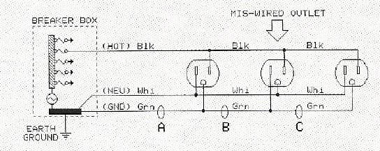
But, as shown in the schematic directly below, a simple outlet wiring error that swaps the neutral and safety ground conductors allows load current to flow in the safety ground wiring.
When equipment load currents of 15 or 20 amps flow in the safety ground wiring, voltage drops as high as 3 volts can occur over its length (assuming the safety ground wiring is the same gauge as line and neutral). Although the outlet is still functional and safe, this error can cause system ground noise to increase by a factor of 100 or about 40 dB!
Simple outlet testers cannot find the problem because they test only for voltages at the outlet. Since neutral and safety ground are bonded together at the main breaker panel, they are indistinguishable to these testers. Even more sophisticated testers cannot reveal the error.
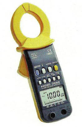
However, if nominal loads (say 100-watt light bulbs) are plugged into each of the outlets on the branch circuit, a clamp-on ammeter like the one shown here can quickly reveal and locate the mis-wiring by measuring current at points A, B, and C.
Referring to the schematic, abnormally high currents would be measured at locations A and B but not C.
Bill Whitlock served as president and chief engineer of Jensen Transformers for 25 years, and now serves as a consultant the company for new product development and technical support. He is also recognized as one of the foremost technical writers in professional audio.
Read more articles by Bill about best AC and electrical practices here.


