
Before beginning the design process for a business sound system, identify what the customer needs and expects:
Fidelity Expectations. Does the client want a good, basic system; something a little better than average; or maximum bandwidth and maximum fidelity?
Sound-Level Requirements. Will the system be used strictly for background music, or does it really need to rock?
Usage. What kind of music will be played through it? For example, if it’s urban funk, then you’re going to have to think about the bass quality and SPL capability.
Form. Do they want in-ceiling or on-wall loudspeakers?
Coverage Requirements. How even do they want the coverage to be? Is it OK for it to perceptibly vary in volume within the space, or do they want it even throughout? Are there areas that don’t need to be covered at all, or where they might want lower SPL, such as the cash register area in a store?
Low-Frequency Coverage. How even does low-frequency coverage need to be? If you’re using subwoofers, is it okay to use a small number, meaning the sound will be loudest close to the sub(s) and softer elsewhere, or do the subs need to cover evenly?
Paging. Do they need paging? If so, how important is paging intelligibility?
Zones. How many zones need separate volume controls, different source controls or paging assignment?
Benchmarking. Do they want this system in order to keep up with a key competitor? If so, this can give you a benchmark.
Cost. Does the system they want fit into their cost requirements? If not, which functions can be adjusted to meet the budget, or is a budget reassessment advisable?
Collect this information and confirm your understanding with your customer before you start designing. You’ll have a much clearer idea of how to proceed when you know what your customer needs.
As we start thinking about the design, we need to then translate our client’s requirements into specific goals for coverage, sound levels and bandwidth. Once these requirements are identified, we can start thinking about loudspeaker and component selection, speaker layout patterns and speaker density.
We need to be able to correctly commission the system after it is installed, ensuring proper settings and optimal performance. Let’s start here with loudspeakers, and in future installments, I’ll look at other issues, such as loudspeaker layout, as well as SPL and equalization. The importance of collecting key information and confirming your understanding of it with the customer before the design process commences.
Ceiling Loudspeakers
Have you ever heard, or followed, rules of thumb like “space ceiling loudspeakers as far apart as the ceiling is high” or “as far apart as the distance from the listener’s ear to the ceiling?” While they are simple to follow, they aren’t very practical. The conditions upon which these rules were supposedly based—the needs of commodity-grade systems—just aren’t what’s required today. No hard-and-fast rule is going to apply in all cases. You need to find out what the customer needs before you start making plans around loudspeakers.
The main objectives in deciding about the placement pattern and density of loudspeakers in a distributed system are covering the area effectively, providing sound that is audible and intelligible over the entire area, and making sure the system is capable of sustaining whatever sound pressure level the application requires.
A Common Misunderstanding
The following misunderstanding about the coverage angle specification of loudspeakers can easily result in system design mistakes. First, let me clarify that the term “coverage angle” is the angle at which the sound level is 6 dB down from the on-axis sound level.
It’s very common to see a polar coverage spec of the “coverage angle” on a spec sheet and assume that the speaker will actually cover this angle when installed. It seems like it would be the case, doesn’t it? But the truth is that loudspeakers actually cover less area than their spec sheets would imply.
Polar Vs Listening-Plane Coverage
There are two different types of coverage measurements that get confused for one another.
It’s standard in the loudspeaker industry to state the coverage in a polar pattern—in a sphere that is 1 meter from the loudspeaker in all directions.
The angle where the sound level is down 6 dB from the on-axis level is called the edge of the polar coverage pattern. This is what appears on spec sheets.
It’s a legitimate specification, but it does not represent what the coverage will be over a flat listening plane, as in any room, because it doesn’t take into account the difference in distances that people are from the speaker.
For loudspeakers projecting from a ceiling onto a flat listening plane, the sound has to travel farther off-axis (to the sides) than it travels on-axis (directly below the speaker) resulting in a much greater drop-off of sound level off-axis.
The result is that the actual coverage angle (at -6 dB) on the listening plane is more narrow than the polar spec. Some ceiling loudspeaker manufacturers use their polar measurement to claim extraordinarily wide coverage. Do not use this specification to lay out coverage patterns of ceiling loudspeakers!
To Illustrate, imagine a loudspeaker with a 180-degree polar spec. If you were to incorrectly interpret this as 180-degree coverage on the listening plane, then one loudspeaker would be all you would ever need for any application. Imagine a single loudspeaker trying to cover an entire department store or restaurant. In fact, you will see that unless a loudspeaker can send more sound to the sides than it does directly on-axis, it never covers more than 120 degrees.
The system designer needs to work with the actual coverage over a flat listening plane because that is the plane in which we live, listening at a height of 3 to 6 feet above the floor, depending on how tall we are and whether we’re standing or seated. This is called the listening-plane coverage specification of the loudspeaker. The listening-plane spec represents the reality of the speaker’s coverage for the listeners. Laws of physics dictate that the listening-plane coverage is always more narrow than the polar coverage pattern.
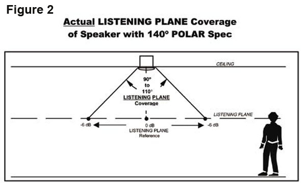
Figure 1 shows a loudspeaker that has a 140-degree polar coverage (i.e., its 6 dB down points). We can see that it would be a mistake to assume that this speaker can cover 140 degrees over the listening plane. In fact, the level at the edges of a 140-degree pattern is actually more than 15 dB down compared to on-axis — not 6 dB down.
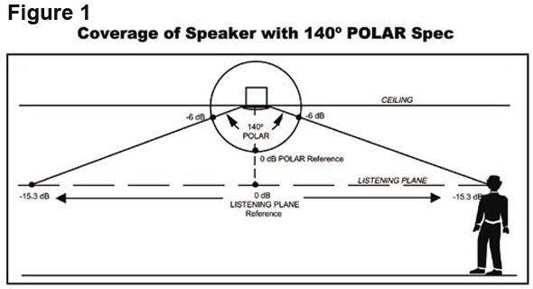
It’s interesting to note that the same proportions hold true for any ceiling height: No matter how high the ceiling is, the off-axis distance is farther away by the same proportion. So for the loudspeaker in this example, whether the ceiling height is 8 feet or 20 feet, the listener who is at the edge of the 140-degree pattern, who you might have thought would be at the 6 dB down point is really at the 15 dB down point!
The actual listening-plane coverage depends on the polar plot of each loudspeaker. On average, the coverage of the listening plane from a speaker with a 140-degree polar coverage is usually between 90 degrees and 110 degrees (see Figure 2).
Converting Coverage
How do you convert polar coverage to listening-plane coverage as you design sound systems? There are two ways.
One is to use a computer program that does the conversion for you. If you have a copy of EASE, place the loudspeaker in the ceiling, set the listening plane height to the typical application height and see how much area it covers (at the 6 dB down point).
Usually that’s enough, but you can also do a little bit of math and figure out what the real listening plane coverage angle of the loudspeaker is. JBL Pro created a simple program, “Distributed System Design,” to do this same conversion for its loudspeakers. I also think there are some programs available that have a more generic database of loudspeakers.
The second way to compute the listening-plane coverage is to start with the exact polar plot of the speaker and use a conversion table. (Real polar plots directly from test equipment are more accurate than an artists’ re-drawing.) Polar plots are usually normalized to the on-axis value, which is usually labeled “0 dB.” For every angle off-axis, there is a “difference-figure” between this normalized on-axis value and the volume at that angle.
To convert to listening-plane coverage, add the dB Correction Factor figure from Table 1 for that angle off-axis to the figure from the polar plot. If you’re doing this correctly, the coverage pattern is getting more narrow than the original polar plot.
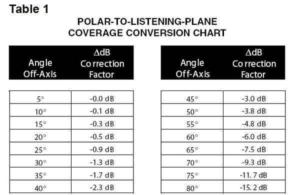
By using the actual polar plot of the speaker and applying these correction factors from the chart, the angle that results in a figure of -6 dB is the angle of coverage for the loudspeaker. This angle is the real 6 dB-down angle for that loudspeaker when it is projected onto the listening plane. Remember that this coverage angle is valid regardless of the ceiling height.
Example 1. If we look at the polar plot of our hypothetical speaker with 140-degree polar coverage, we see that at 70 degrees off-axis (140 degrees total for both sides) the level is down 6 dB compared to the on-axis level.
By looking at the polar-to-listening-plane conversion chart, we need to add -9.3 dB to this -6 dB figure to find the actual level on the listening plane at this off-axis angle.
We find that the level of this 140-degree loudspeaker (as specified by the polar coverage) is actually -15.3 dB, not -6 dB, down at 70 degrees off-axis.
Therefore, listeners located at this off-axis angle will hear sound that is more than 15 dB down from the level they hear when they pass directly underneath the loudspeaker. This is a very large difference.
To find the actual 6 dB down point of the speaker for the listening plane, take the actual polar plot of the speaker and at every increment of 5 degrees off-axis, apply the correction factors from the polar-to-listening-plane conversion chart.
The 6 dB-down angle is that angle at which the new figure reads -6 dB (polar dB down plus the additional dB down from the correction factor). While the final resulting angle depends on the actual polar plot of the loudspeaker, it can generally be said that most loudspeakers with a nominal polar coverage of 140 degrees can be expected to reach -6 dB between 45 degrees and 55 degrees off-axis, resulting in an actual listening-plane coverage between 90 degrees and 110 degrees.
Example 2. Let’s look at a loudspeaker that has a 180-degree polar coverage. Let’s further assume that it is a mythical “perfect” loudspeaker where the volume doesn’t go down at all at any angle. Its polar pattern when placed in a ceiling is a perfect half-circle.
To find the real 6 dB-down point, we apply the correction factors and find that at 60 degrees off axis (120 degrees coverage), the sound is 6 dB down (again, polar dB down plus the additional dB down from the correction factor).
Therefore, the real listening-plane coverage of a perfect 180-degree loudspeaker is only 120 degrees. Now, given the fact that speakers with a “spec” of 180-degree polar coverage can actually be down as much as 6 dB at the 180-degree point and still have a spec of 180 degrees, the fact is that virtually all loudspeakers have a real coverage of less than 120 degrees.
Further Factors
A couple of interesting points follow from this discussion.
First, let me point out that subwoofers resemble Example 2. They have omnidirectional coverage of 180 degrees (when in the ceiling). So they, too, have listening-plane coverage of only 120 degrees.
Second, while it is not within the scope of this article, you can see that this principle applies to all loudspeakers projected anywhere. The fact that the listening plane in any venue is hardly ever a perfect sphere around the loudspeaker means that you will almost always be projecting loudspeakers onto a somewhat listening plane; and the coverage is almost always going to be more narrow than what the polar spec would indicate.
A student once mentioned to me that he had done some church designs taking a protractor and scribing the coverage pattern onto the floorplan drawing. When the system was installed, they had more holes than expected. After a class on coverage, he realized that it is a matter of projecting a loudspeaker onto a listening plane so that the actual coverage is going to be narrower than what he plotted.
Frequency Coverage
Let’s talk about broadband vs. single-frequency coverage specifications. You may have done all the conversion work above, and it might apply only to one frequency!
If the loudspeaker does not have similar coverage at all frequencies, then it covers wider or narrower angles at different frequencies. Some ceiling loudspeakers specify their coverage only at a particular frequency, often at 2 kHz. The reason 2 kHz if often used is that 2 kHz is the most important octave for speech intelligibility. However, other octaves a still very important for intelligibility and all octaves are important for music.
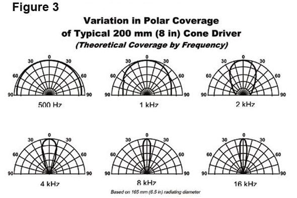
Many types of loudspeakers do not provide even coverage throughout the audio spectrum. Every spot within the listening area ends up with a different frequency response and different sound level (see Figure 3). In addition to this making it impossible to set a coverage angle, it also defeats attempts to equalize because whatever spot you choose to set your EQ, it’s different everywhere else.
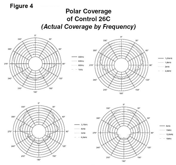
But there is a good solution: Choose loudspeakers that cover similar angles throughout a broad frequency range. This is one advantage of having loudspeakers with small diameters (so they don’t start beaming until a very high frequency), or having multiway loudspeakers with goo crossover networks where higher frequencies are reproduced by small drivers (tweeters or compression drivers for high-power loudspeakers).
Horns on the high-frequency drivers further help in providing even coverage at all frequencies. See Figure 4 for a well controlled loudspeaker.
Review
Let’s take one more look at the old rule of thumb that says to space the loudspeakers as far apart as the distance from the listener to the loudspeaker.
First, this rule was based on an incorrect assumption that all loudspeakers covers 90 degrees. Even for loudspeakers where this coverage is true for some frequencies, it may not be true for all frequencies.
In today’s high-quality sound systems, you need to consider real coverage, not polar or incorrectly assumed coverage.
Next time I’ll focus on SPL and equalization of distributed systems.
Published with permission by JBL Professional.