
Most of us have heard of the electronic crossover. This familiar concept is in the electronic (or digital) domain and deals with frequency response of a system.
Certain drivers will take responsibility to reproduce certain frequencies, and at the crossover, will share in producing sound in a certain range with another source. As the frequency extends in one direction or another beyond it, one driver will take over. The amount of frequency content that is shared is the result of the slope and type of crossover.
The less considered type is called the acoustic crossover. This is a point in (inner) space where two signals from separate sources combine at equal level. I’ll be talking about points in earthly space from here on – sound doesn’t do to well in outer space.
Different Results
Depending on the phase relationship of each frequency emitted, there will be different results in amplitude (summation or cancellation) of each frequency at that spot. A common step in setting up a sound system is to phase align the main loudspeakers to at least one subwoofer. We’re managing the interaction of the low frequencies of the mains at the same level as the higher frequencies of the subs.
We surely don’t want cancellation where they arrive at the same level in the frequency range because we don’t want dips in the frequency response of the total system. This phase alignment will occur at several spots in a room. The sound will combine and be even in response as the rest of the frequency range.
To go hunting for this spot is a waste of time because even if you did find it within a reasonable time frame, the odds of using that spot for your mix position is very slim. The odds of it behaving well at your pre-decided mix position is not great either.
Sound techs and engineers have several methods for combating this issue and creating a predictable response at a chosen spot in the room. One is a physical displacement. To take a measurement at your desired spot for a phase-aligned crossover, check the results, move the loudspeakers and then check again would be just awful. However, if you don’t have a processor or digital console, it might be necessary.
The other way to steer the sound pressure level (SPL) of mains and subs, and cause the desired frequency response at the acoustic crossover to move to your intended spot, is to introduce delay to one of the sources. This has complications in a large space where there’s an audience, so as an example, let’s look at a project studio (my own,) where the response of the whole sound system needed to be “just so at only one point for one person. (The mix position, for me.)
We’ll use this example to examine what’s happening when loudspeakers are steered with delay. I had to re-scale some things and use different loudspeakers for this visual mock-up, but I’ve overlaid the SPL plots with real measurements.
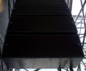
There are two mains as well as a sub in the corner. Figure 1 provides the top-down view (“plan view”). With each change, look at the “Mix Position” and observe the color of the SPL at that point. There will be a change in color for each 3 dB change in level.
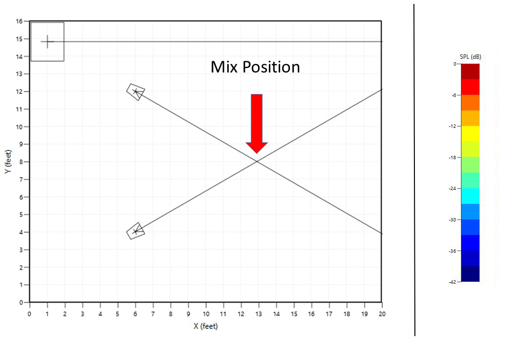
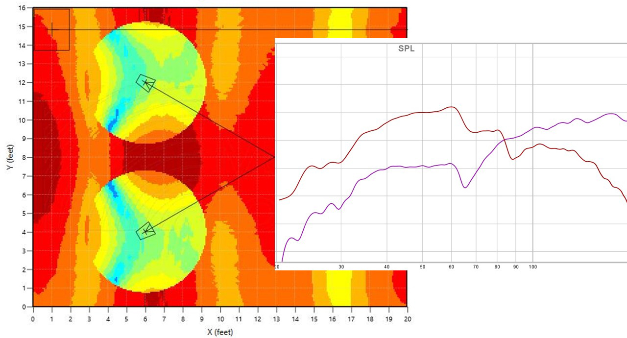
Figure 2 depicts 90 Hz in color. This is the center point for the frequencies that I want to combine and sum in the electronic crossover region. I’m looking for summation gain from 80 to 100 Hz. The red trace is sub and purple trace is the mains. At the mix position, the SPL level (mains only in this picture) is bright red.
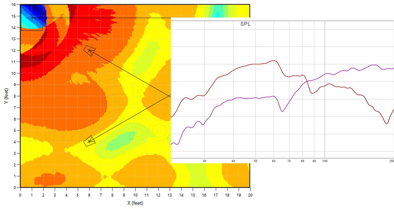
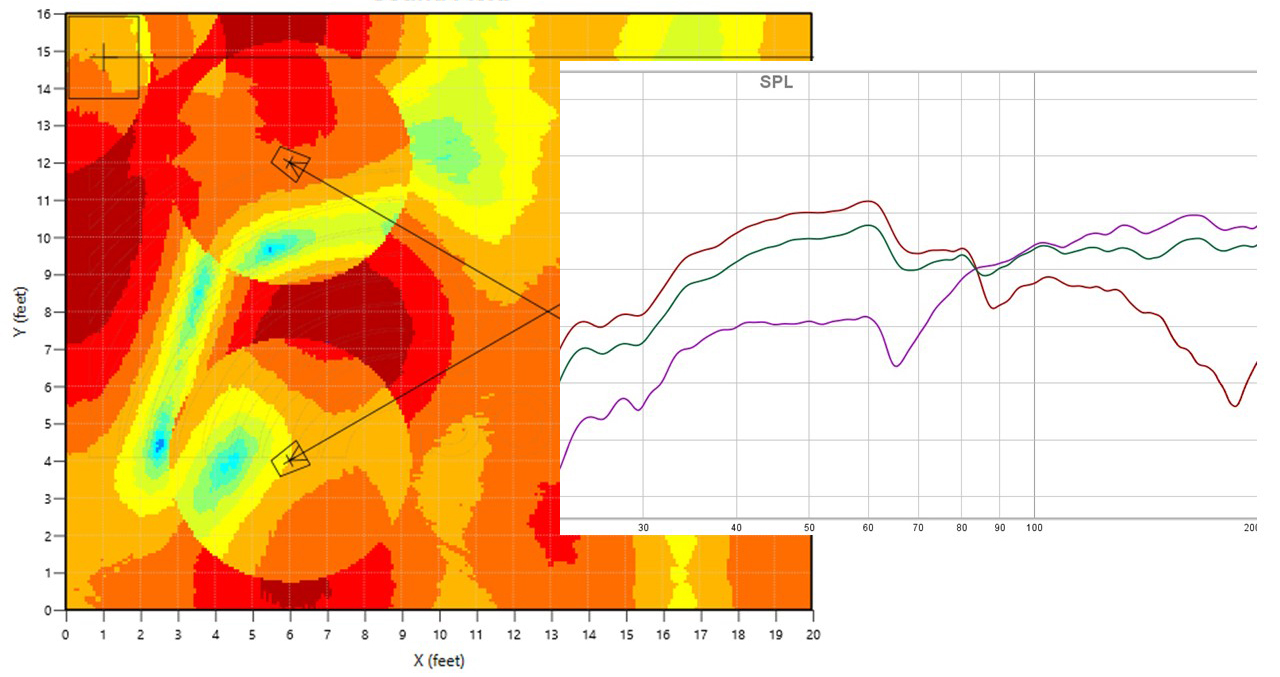
At the mix position in Figure 3 (sub only), SPL is second orange level. When they combine the level is first orange (Figure 4). Unfortunately, as we can see, orange is less level than the red of the mains only (still at 90 Hz), which means we have some cancellation there. The green trace shows all loudspeakers on, and it’s less than the mains in level at 90 Hz. This is happening because of the phase relationship at our mix position.
Making It Work
To fix this issue, we need to add delay to align the phase and steer the SPL to combine at the mix position from 80 to 100 Hz. In reality, the sub was at a different point in its phase rotation because it’s farther away. I looked at the result of delaying the mains a bit but ended up going with flipping the polarity of the sub and then adding delay to it. (Figure 5 shows before the alignment, while Figure 6 is the after view.)
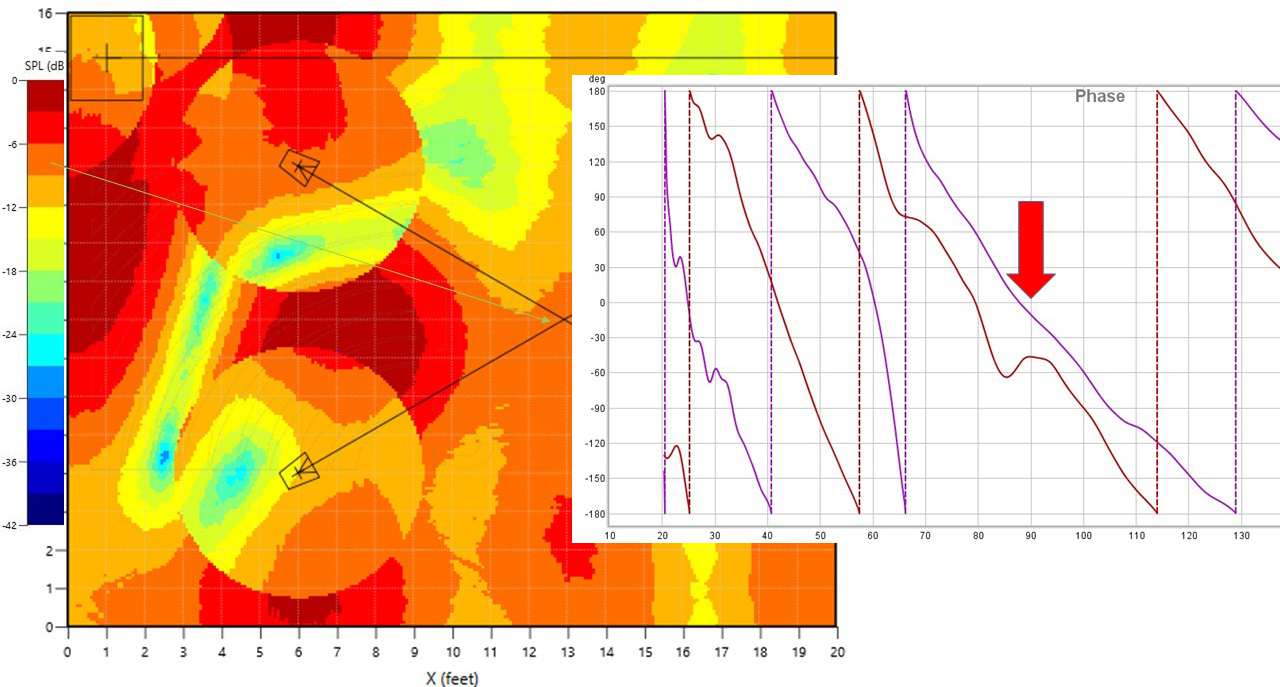
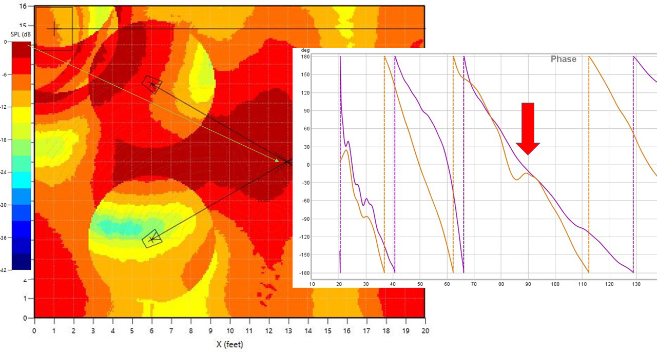
The new phase relationship at 90 Hz is shown in Figure 6. Now we can see that the mix position is in the dark red color. This means that there is summation there and is more than just the mains or sub on their own.
Figure 7 provides the frequency response. Our measurement (blue trace) shows we have summation gain from 70 to over 100 Hz and the SPL plot shows the summation holds up to 1 foot (.304 meter) to the left of the mix position, 3 feet (.914 meter) to the right, 7 feet (2.13 meters) in front and several feet to the rear.
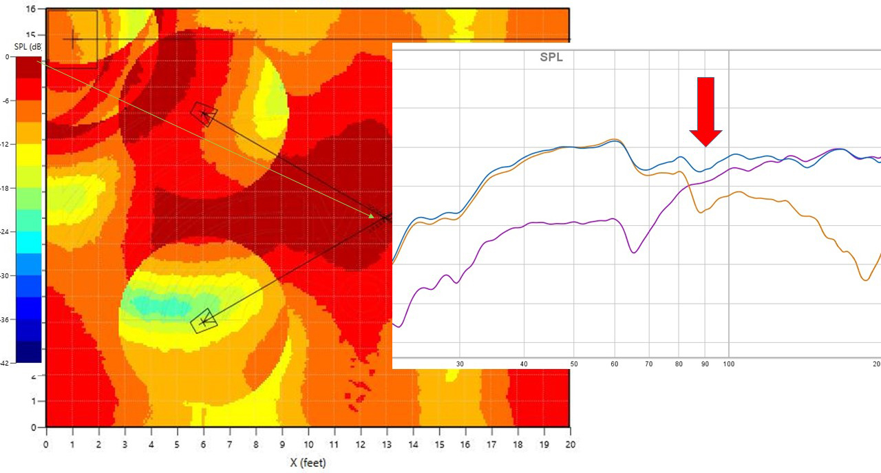
It would probably be even more symmetrical if there were two subs, one in each corner. Also, if we were to place a couch for the artist or producer along the rear wall, it appears that there would be pretty good summation in that regions as well.
This holds up if we were to look at the SPL plot from the side, back or front. The analyzer works in 3D and takes all incidence of sound pressure into account. However, we have to look at it in 2D at this point in time.