What does the shield do?
The copper shield of a coaxial cable acts as the return conductor for the signal current and as a barrier to prevent interference from reaching the “hot” center conductor.
Unwanted types of interference encountered and blocked with varying degrees of success by cable shielding include radio frequency (RFI) (CB and AM radio), electromagnetic (EMI) (power transformers) and electrostatic (ESI) (SCR dimmers, relays, fluorescent lights).
What makes one shield better than another?
To be most effective the cable shield is tied to a ground—usually a metal amplifier or mixer chassis that is in turn grounded to the AC power line. Cable shielding effectiveness against high-frequency interference fields is accomplished by minimizing the transfer impedance of the shield.
At frequencies below 100 kHz, the transfer impedance is equal to the DC resistance—hence, more copper equals better shielding. Above 100 kHz the skin effect previously referred to comes into play and increases the transfer impedance, reducing the shielding effectiveness.
Another important parameter to consider is the optical coverage of the shield, which is simply a percentage expressing how complete the coverage of the center conductor by the shield is.
What are the characteristics of the three basic types of cable shields? Which is best?
A braided shield is applied by braiding bunches of copper strands called picks around the insulated, electrostatically shielded center conductor. The braided shield offers a number of advantages.
It’s coverage can be varied from less than 50 percent to nearly 97 percent by changing the angle, the number of picks and the rate at which they are applied. It is very consistent in its coverage, and remains so as the cable is flexed and bent. This can be crucial in shielding the signal from interference caused by radio-frequency sources, which have very short wavelengths that can enter very small “holes” in the shield.
This RF-shielding superiority is further enhanced by very low inductance, causing the braid to present a very low transfer impedance to high frequencies. This is very important when the shield is supposed to be conducting interference harmlessly to ground. Drawbacks of the braid shield include restricted flexibility, high manufacturing costs because of the relatively slow speed at which the shield-braiding machinery works, and the laborious “picking and pigtailing” operations required during termination.
A serve shield, also known as a spiral-wrapped shield, is applied by wrapping a flat layer of copper strands around the center in a single direction (either clockwise or counter-clockwise). The serve shield is very flexible, providing very little restriction to the “bendability” of the cable. Although its tensile strength is much less than that of braid, the serve’s superior flexibility often makes it more reliable in “real-world” instrument applications.
Tightly braided shields can be literally shredded by being kinked and pulled, as often happens in performance situations, while a spiral-wrapped serve shield will simply stretch without breaking down. Of course, such treatment opens up gaps in the shield which can allow interference to enter. The inductance of the serve shield is also a liability when RFI is a problem; because it literally is a coil of wire, it has a transfer impendance that rises with frequency and is not as effective in shunting interference to ground as a braid.
The serve shield is most effective at frequencies below 100 kHz. From a cost viewpoint, the serve requires less copper, is much faster and hence cheaper to manufacture, and is quicker and easier to terminate than a braided shield. It also allows a smaller overall cable diameter, as it is only composed of a single layer of very small (typically 36 AWG) strands. these characteristics make copper serve a very common choice for audio cables.
The foil shield is composed of a thin layer of mylar-backed aluminum foil in contact with a copper drain wire used to terminate it. The foil shield/drain wire combination is very cheap, but it severely limits flexibility and indeed breaks down under repeated flexing. The advantage of the 100% coverage offered by foil is largely compromised by its high transfer impedance (aluminum being a poorer conductor of electricity than copper), especially at low frequencies.
What type of shield works best against 60-cycle hum from power transformers and AC cables?
The sad truth is that the most offensive “hum-producing” frequencies (60 and 120 Hz) generally emitted by transformers and heavy power cables are too low in frequency to be stopped by anything but a solid tube of ferrous (magnetic) metal—iron, steel, nickel, etc.—none of which contribute to the flexibility of a cable! For magnetically coupled interference, the only solution is to present as small a loop area as possible. This is one of fhe reasons that the twisted-pair configuration generally used in balanced-line applications became popular.
Fortunately the high input impedances generally found in unbalanced circuits minimize the effects of such interference. Don’t run instrument cables parallel to extension cords. Don’t coil up the excess length of a “too long” cable and stuff it through the carrying handle of a amp—this makes a great inductive pickup loop for 60 Hz hum!
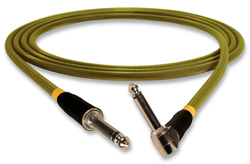
What does the outer jacket do? What is it made of?
The jacket is both armor and advertisement; it protects the cable from damage and enhances the marketability of the assembly. As armor, the jacket must resist abrasion, impact, moisture and sometimes hostile chemicals (Bud Light, for instance).
As advertisement, it may be distinctively colored or printed with the name of the manufacturer or dealer for product identification. The materials used for jacketing are the same type as those used for the inner insulation (thermoset or thermoplastic), but the choice is dictated less by electrical criteria and more by physical durability and cosmetic acceptability.
What is the best cable jacketing material?
For years rubber or neoprene were preferred for their superior abrasion resistance and flexibility, but modern thermoplastic technology has produced a number of PVC compounds that are soft and flexible but also very tough. As previously noted, thermoplastic processing is cheaper, faster and more predictable than that for thermoset materials. Only very specialized situations requiring oil or ozone resistance or extremes of temperature and climate demand neoprene or Hypalon jacketing.
The use of PVC has two other major advantages. PVC is not as elastic as rubber or neoprene, and this lack of “stretch” lends additional tensile strength to the resulting assembly by taking some of the strain that would otherwise be borne solely by the center conductor. This has made a dramatic improvement in the reliability of currently manufactured instrument cables.
The other important property of PVC is its almost limitless colorability. Once found only in gray or “chrome vinyl,” PVC-jacketed cable now ranges from basic black through brilliant primary colors to outrageous “neon” shades of pink and green.
BIBLIOGRAPHY
• Ballou, Greg, ed., Handbook for Sound Engineers: The New Audio Cyclopedia, Howard W. Sams and Co., Indianapolis, 1987.
• Cable Shield Performance and Selection Guide, Belden Electronic Wire and Cable, 1983.
• Colloms, Martin, “Crystals: Linear and Large,” Hi-Fi News and Record Review, November 1984.
• Cooke, Nelson M. and Herbert F. R. Adams, Basic Mathematics for Electronics, McGraw-Hill, Inc., New York, 1970.
• Davis, Gary and Ralph Jones, Sound Reinforcement Handbook, Hal Leonard Publishing Corp., Milwaukee, 1970.
• Electronic Wire and Cable Catalog E-100, American Insulated Wire Corp., 1984.
• Fause, Ken, “Shielding, Grounding and Safety,” Recording Engineer/Producer, circa 1980.
• Ford, Hugh, “Audio Cables,” Studio Sound, Novemer 1980.
• Guide to Wire and Cable Construction, American Insulated Wire Corp., 1981.
• Grundy, Albert, “Grounding and Shielding Revisited,” dB, October 1980.
• Jung, Walt and Dick Marsh, “Pooge-2: A Mod Symphony for Your Hafler DH200 or Other Power Amplifiers,” The Audio Amateur, 4/1981.
• Maynard, Harry, “Speaker Cables,” Radio-Electronics, December 1978,
• Miller, Paul, “Audio Cable: The Neglected Component,” dB, December 1978.
• Morgen, Bruce, “Shield The Cable!,” Electronic Procucts, August 15, 1983.
• Morrison, Ralph, Grounding and Shielding Techniques in Instrumentation, John Wiley and Sons, New York, 1977.
• Ott, Henry W., Noise Reduciton in Electronic Systems, John Wiley and Sons, New York, 1976.
• Ruck, Bill, “Current Thoughts on Wire,” The Audio Amateur, 4/82.
Thanks to Pro Co Sound for this article.