The 20 AWG center conductor has become quite standard, normally in the form of 26 strands of 34 conductor has become quite standard, normally in the form of 26 strands of 34 AWG(26/34) or 41 strands of 36 AWG (41/36).
A 20 AWG conductor has a breaking point of approximately 31 lbs. Reducing conductor size to 22 AWG reduces breaking point to about 19 pounds (a reduction of 39 percent); increasing it to 18 AWG increases the strength to over 49 pounds (an increase of 58 percent).
The most common cause of failure for instrument cables is broken center conductors.
What are the differences between tinned copper and bare copper stranded conductors?
Sometimes the individual strands of the center conductor are run through a bath of molten tin before assembling them into a wire. Tinned copper wire is often easier to solder, especially if a lengthy (months to years) shelf life is required, because the tin coat prevents copper oxides from forming. If the cable is to be used immediately upon manufacture pre-tinned strands are not required and add unnecessary expense.
Furthermore, an electrical phenomenon known as skin effect makes the use of tinned conductors a potential threat to the high-frequency signal-carrying properties of the cable. However, the aging effects of the formation of copper oxides on untinned conductors may also cause a gradual deterioration of performance.
What is skin effect and how does it affect tinned copper?
Briefly, skin effect is caused by the magnetic field generated by the current flow in the cable causing electron flow to be concentrated more and more on the outer surface of the conductor as frequency increases. If this outer surface is coated with tin, which has higher resistance than copper, the cable will have a falling high-frequency response and act as an attenuator.
What is oxygen-free and linear-crystal copper? How do they affect sound in cables?
There is a continuing debate concerning the use of oxygen-free and linear-crystal copper wire. These types of wire contain lower levels of oxide impurities and fewer crystal boundaries than standard copper. Since these impurities form tiny semiconductors within the cable, the theory is that the cable itself introduces signal distortion, especially of low-level “detail” information. These claims have been very difficult to document with scientific test equipment, but numerous listening tests suggest there is something to them.
What materials are used for insulation of the center conductor?
The insulation that surrounds the center conductor can be made from thermoset (rubber, E.P.D.M., neoprene, Hypalon) or thermoplastic (polyethylene, polypropylene, PVC, FPE) materials. The thermoset materials are extruded over the conductor and then heat-cured to vulcanize them. This process yields a very high melting point which makes soldering very easy, but the vulcanizing stage adds to the cost and introduces unpredictable shrinkage which can make it very difficult to maintain the desired wall thickness.
Thermoplastic insulations are cheaper to process but will return to a liquid state when overheated, requiring great care during soldering when used to insulate large conductors. The insulation of choice for instrument cable has largely shifted from rubber or E.P.D.M. to high-density polyethylene, with cost being a major factor.
How does the insulation affect flexibility?
The insulation material and its thickness can be very dominant in determining the flexibility of the cable. A finely-stranded conductor insulated with a stiff compound will behave much like a solid conductor, as will a conductor insulated with a very thick layer of a more flexible compound. The thinner the insulation is, the more flexibility it allows in the overall cable.
How thick does the insulation need to be?
The basic electrical requirement for insulation thickness is called dielectric strength and is determined by the cable’s working voltage. The voltages involved in instrument cable applications are very low and very little dielectric strength is necessary to prevent the insulation from breaking down. However, a very important consideration when the cable is to be used for instruments like electric guitars is the amount of capacitance between the center conductor and shield.
What is capacitance and what does it do?
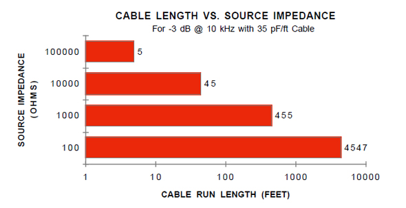
Capacitance is the ability to store an electrical charge. In cables, capacitance between the center conductor and shield is expressed in picofarads per foot (pF/ft.), with lower values indicating less capacitance. Combined with the source impedance, cable capacitance forms a low-pass filer between the instrument and amplifier; that is, it cuts high frequencies, much as the instrument’s tone control does.
Why is low-capacitance cable an advantage? How can cable capacitance be eliminated? How long of a cable can I run before I lose high frequencies?
Lower cable capacitance allows more of the natural “brightness,” “presence,” or “bite” of an instrument to reach the amp, which in turn allows the treble controls to be run lower, reducing “hiss” and other unwanted noise. High-frequency loss from the cable becomes audible and objectionable depending on the source, the amplification and other circumstances. Raising the source impedance or increasing the length of the cable increases the loss; there is no point at which high-frequency loss suddenly appears or disappears.
Guitars typically have much higher source impedances at higher frequencies because of the inductive nature of their pickups, which aggravates the effect of cable capacitance. A guitar will often sound noticeably “muddier” when run through a 40-foot cable, whereas keyboard instruments, samplers, mixers and other line-level devices with low source impedances can usually drive cable runs of hundreds of feet without problems.