
Audio professionals will tell you that compression is an essential part of their mixes – if used correctly. But using it correctly starts with understanding what the controls are doing. In this first article in a series on compression, I’m going to explore the basic compression controls and how they function. Later we’ll talk about how to use it in live applications.
Compression reduces dynamic range, or the difference between the loud and quiet parts of the signal. Sometimes the voices and instruments we’re amplifying have more dynamic range than we need to fit them into a loud mix, or to stay comfortable while also intelligible (balancing “I can’t understand,” with “Ouch! That hurts!”).
Compression becomes an automatic level control, much like our fingers (digits) riding a fader up and down (the original digital compressor = fingers… digits, get it?) But the compressor makes these changes automatically without requiring our full attention and a finger on the fader.
We measure audio levels and dynamic range in decibels, which without a specific reference level, just mean changes from one level to another. We’ll be using this unit of measurement more soon.
Inputs To Outputs: The Ratio
The compressor lets us choose how much we want it to turn the output signal down as the input signal goes up. This is called the ratio, and we write it as X:1, where X answers the question, “How many more decibels of input do I need to get one more decibel of output?” If we have a ratio of 2:1, we’d only get one more decibel of output for every two decibels of additional input. Our compressor turns down the signal more and more as the input level goes up.
A great starting place for compression ratios on audio inputs is 3:1 or 4:1. If the ratio is at or above 10:1, it’s typically referred to as a limiter.
I’ve Reached My Threshold
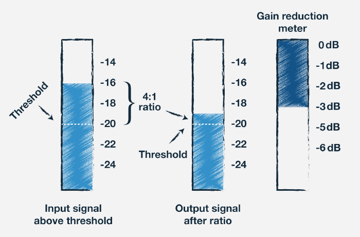
It’s rare that we want to apply the ratio to the full dynamic range of the signal, so the compressor has a threshold control that allows us to divide the dynamic range into two sections. Above the threshold we apply the ratio, and below the threshold, we don’t apply the ratio or have a 1:1 ratio (Figure 1).
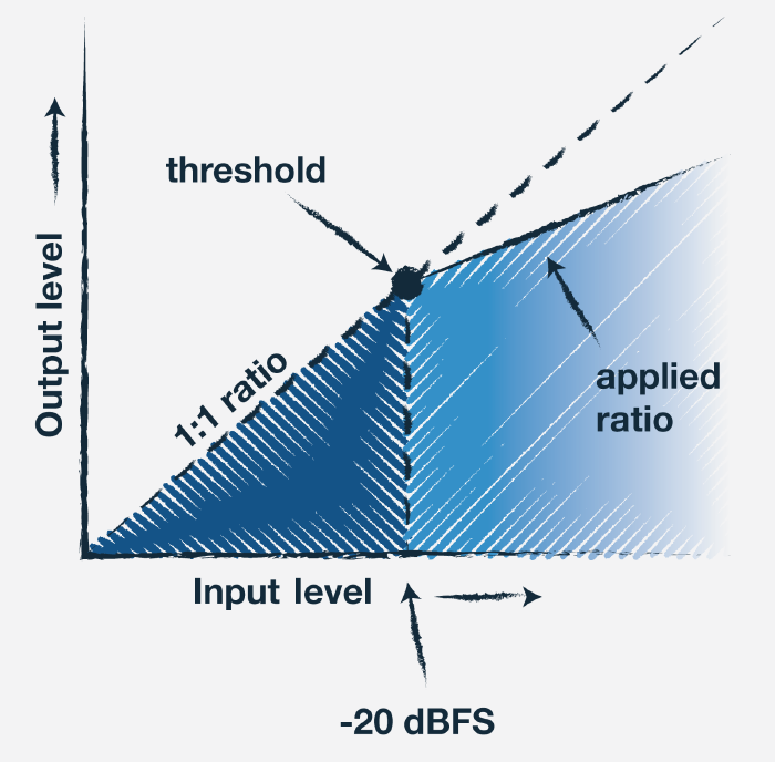
On analog and digital compressors alike, you’ll see this referenced as a decibel level as well, but this is related to 0 dB VU for analog compressors (or 0 dBFS). So, if the compressor’s threshold is set to -20 dBFS, it means that when the input signal is below -20 dBFS, there’s no ratio applied to the signal, but as the input signal goes over -20 dBFS, it will apply the ratio.
While audio moves and changes over time, like video, let’s take some snapshots to try and understand what’s “under the hood” of compressors.
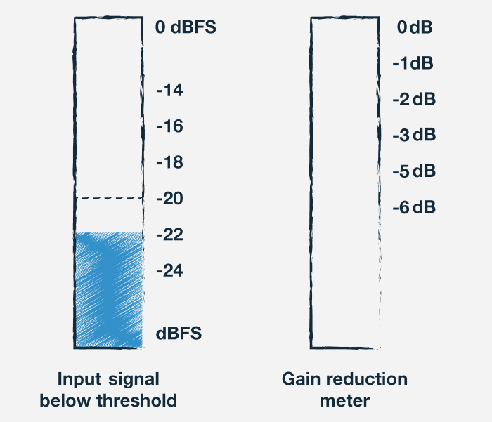
We’ll start by assuming our ratio is 4:1 (always a good starting place in live sound), and our threshold is set to -20 dBFS. If the signal is at -22 dBFS (bigger negative numbers means a lower signal level), the signal is below the threshold, so the compressor’s ratio isn’t applied (Figure 2). Every decibel of change of input level up or down from here gets the exact same output level, so the output level will be -22 dBFS as well.
Now let’s take another snapshot where the input signal level is at -16 dBFS. Will the output level go up to -16 dBFS? No, the compressor is going to apply the ratio to the signal’s output level. The input signal is 4 dB above the threshold, and since there’s a 4:1 ratio, we’re only getting 1 additional decibel of output above the threshold, making our output level -19 dBFS (Figure 3).
Gain Reducation
The compressor shows us this level change – the difference between the input level and the output level – as gain reduction. If the meter shows 0, that means the compressor isn’t “pushing down” the output level at all. In the previous example where the input signal is at -16 dBFS and the output level is at -19 dBFS, the gain reduction meter will show -3 dB of gain reduction.
It’s a good idea to keep an eye on the gain reduction meter. It shows us what’s going on with the compressor while the input is at different levels. If it’s showing a lot of gain reduction even while the input signal isn’t very loud, it may mean that you’ve set the compression threshold too low and need to raise it for it to sound more natural.
Make-Up Gain
Recall from the beginning of the article that the goal with compression is to reduce the dynamic range. To think of it in context, before compressing the signal, we mix our input so that its maximum level is appropriate to not hurt the listener or fit within the context of the other inputs. When we apply compression, it allows us to turn down the very loudest parts of that signal so we can turn the entire signal up, effectively making the quieter parts louder.
After applying the ratio with the threshold and getting some gain reduction, we’ve only turned down the signal. If the input goes higher, the amount of gain reduction increases as well. So, to get the average signal level back up to where it was before we applied the gain reduction, there’s the output gain, or make-up gain – the gain stage after the gain reduction circuit (Figure 4).

If we don’t add any make-up gain, we can push up the fader to get the level back. But this has two disadvantages. The first is that we might run out of fader, and the farther we go above 0 dB on the fader, the less fine-tuning control. The second is that if we want or need to bypass the compressor, there will be a large level jump.
When applying any kind of processor to the signal, it’s always a good idea to listen in an A/B test to see if the processor is helping the signal sound better or making it sound worse. The problem comes with the way our ears perceive sounds at different levels.
Try this: listen to some music at a nice, full level, and focus on the low end of the bass guitar and the kick drum. Then turn it down a considerable amount and note how the low frequencies aren’t as noticeable. Basically put, when you turn a sound up, it sounds fuller and better, and when you turn it down, it sounds smaller and thinner. Two fellows named Fletcher and Munson developed the Equal Loudness Curve to describe it, and it’s a really illuminating (audioluminating?) phenomenon.
What does that mean for a compressor? It means that to really hear if the compressor is making a signal sound better or worse, we need to keep the compressed and uncompressed signals at a similar average level so as to not deceive ourselves into thinking the louder one sounds better.
After reducing the threshold to apply as much gain reduction as you want to try, use the makeup gain to boost the signal back up, toggling the compressor bypass on and off to make sure that there’s not much of a dip or boost between the two.
So far we’ve been looking at the compressor in a frozen moment of time to understand what it’s doing, but audio signals aren’t static. Their levels change over time. Compressors also have the ability to respond to the audio signal’s changes in input level in the time domain using the attack and release controls.
The attack time is how quickly or slowly the compressor responds to increased input levels. If the attack time is very fast, the compressor will respond almost instantly to any increase in input level. This can take the percussive sounds of a piano hammer striking the string and push that down. On the other hand, there can be a very slow attack time, so the gain reduction on the compressor doesn’t “push” the signal down as quickly as the transient or percussiveness of the signal comes and goes again.
In short, the attack time has to do with whether or not we want the compressor to push down the transients or percussive parts of the signal or not. A faster attack time means we lose (or tame, depending on your goal) more transients, while a slower attack time means we preserve more of the transients (Figures 5a, 5b and 5c).
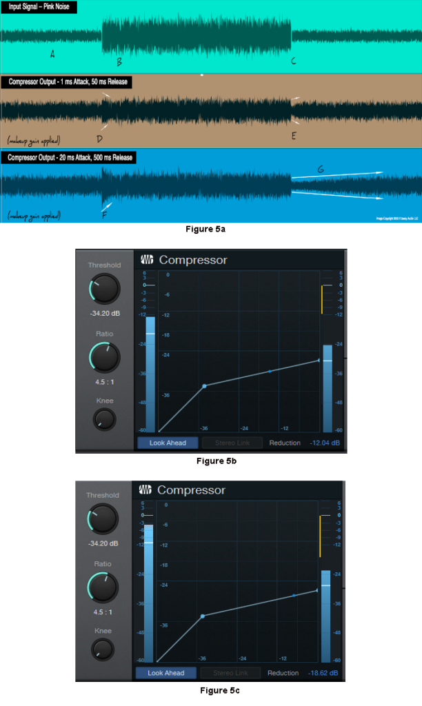
The release time, also known as the recovery time, is how quickly the compressor’s gain reduction responds to decreases in input level. As the input signal level goes down, the new input level is telling the ratio that we need less gain reduction. With a fast release time, the gain reduction reduces (turning it back up) quickly, pushing up the quieter parts of the signal.
A slow release time can make that transition less abrupt. Be careful though – if the release time is too slow, we can inadvertently turn down the quieter parts of the input signal that we want to be louder. If the release time is too fast, we can change the input signal to the point where it sounds unnatural, giving it a “pumping” feeling.
Now that we have a good grasp of what a compressor’s controls are, stay tuned for the next article on how to apply it in musical ways. In summary, we set the input at a comfortable volume so the peaks don’t hurt. Then, we turn down the peaks with the gain reduction and then boost the entire signal back up with the output gain. This puts the loudest parts back in the right spot in the mix, but now the quieter parts of the signal are up there too.