
Editor’s Note: Go here for Part 2 of this article, and here for Part 3.
Compared to electronic audio tests, measuring loudspeakers is complicated. First, to measure sound levels accurately requires precision measurement microphones and supporting electronics, which have a known, stable sensitivity and flat frequency response over the frequency range of interest.
Measurements are further complicated by the interaction of the loudspeaker under test with the test environment. Ideally, we want to measure the direct sound radiated from the device under test (DUT) without any contamination caused by reflections from walls, floors, or ceilings, etc. Special rooms called anechoic chambers are available for this purpose, but they’re very expensive. And even the best ones are usually not fully anechoic at the lowest frequencies of interest.
Physical dimensions are also extremely important in acoustics. The audible frequency range is generally considered to be 20 Hz to 20 kHz. The corresponding range of wavelengths of sound in air at room temperature is 56 feet to 0.68 inch (17.2 meters to 17.2 millimeters).
So, at 20 Hz, a typical loudspeaker is tiny compared to the wavelength of sound, and it behaves like a point source, radiating uniformly in all directions. At 20 kHz, the opposite is true; a typical loudspeaker is large compared to the wavelength and its radiation pattern is radically different in all directions. Further, the wavelength at 20 kHz is close to the diameter of a typical measurement microphone (0.5 inch or 12.7 millimeters), making measurements highly sensitive to small changes in mic position.
Despite the challenges, when recommended procedures are followed using quality test equipment, it’s possible to make good, repeatable loudspeaker measurements. Over the course of this article series, the following loudspeaker measurements will be covered:
— Frequency response
— Sensitivity
— Input voltage/power
— Impedance & Thiele-Small parameters
— Directivity
— Distortion
— Industry Standards
Ideally, standards represent consensus among industry experts concerning measurement conditions and recommended practices that will help to ensure that devices are tested in a meaningful and repeatable way. The key international standard covering loudspeaker measurements is IEC 60268-5, Sound system equipment, Part 5: Loudspeakers [1]. This standard applies to passive loudspeaker drive units and passive loudspeaker systems only; it does not apply to active loudspeakers (built-in amplifiers).
Given the widespread use of powered loudspeakers today, it seems like IEC 60268-5 is due for revision, and indeed, work in that direction is in process. In the meantime, it serves as a useful reference for conducting acoustical and electrical measurements of loudspeaker drive units and loudspeaker systems.
Frequency Response
Frequency response is the single most important aspect of the performance of any audio device. If it is wrong, nothing else matters. – Floyd Toole, 2009 [3]
Frequency response is a “transfer function” measurement. For a device under test (DUT), it represents the magnitude and phase of the output from the DUT per unit input, as a function of frequency. Devices are often compared in terms of the “shape” of their frequency response curves, which typically refers to the magnitude response only (not phase), and in addition normalizes the magnitude to a reference value.
For example, the response magnitude might be normalized to its value at some reference frequency, say 1 kHz, such that the normalized curve passes through 0 dB at 1 kHz. In the case of loudspeakers, the output from the DUT is the sound pressure as measured at a point in space. For passive loudspeakers, the input to the DUT is an amplified voltage signal, and for powered loudspeakers it could be an unamplified voltage or a digital audio signal (transmitted over a digital audio interface such as S/PDIF, HDMI, or Bluetooth, etc.).
Loudspeaker design engineers usually strive for flat frequency response in their designs, to help ensure that source material is faithfully recorded and reproduced without spectral coloration. For electronic audio components, flat frequency response is the norm and is easily achievable. For example, almost any audio amplifier will have a flatness of less than ±1 dB within the audio band (20 Hz to 20 kHz); even ±0.1 dB is not uncommon.
In the case of loudspeakers, achieving flat frequency response is challenging, for a variety of reasons. Multiple drive units of different sizes (and sensitivities) with crossover circuits must be combined to cover a wide frequency range. At some frequencies, drivers interact with the enclosure acoustically. And mechanical resonances in the drive units and/or the enclosure can cause sharp peaks or troughs in the response curve.
As a result, it’s not uncommon to find consumer loudspeakers with deviations from flatness of up to 20 dB over their useful frequency range. Nevertheless, it is possible to achieve a relatively smooth and flat response for loudspeaker systems, and a deviation from flatness of ±3 dB is considered “respectable.” Multiple studies of listener preferences for loudspeakers have shown that trained listeners prefer systems with smooth flat frequency response, both on and off axis, and deep bass [4].
Sound Fields
When conducting loudspeaker measurements, the concept of sound fields is important. Acoustic loudspeaker measurements should be conducted in a free field, which is a region in space around a sound source where sound may propagate freely in all directions with no obstructions.
An idealized example of this is a point source (an object that is small compared to the wavelength of sound radiating from it) located high above the ground and away from any reflective surfaces. When an idealized point source radiates sound in a free field, the sound intensity (sound power per unit area) is inversely proportional to the square of the distance from the source Figure 1.
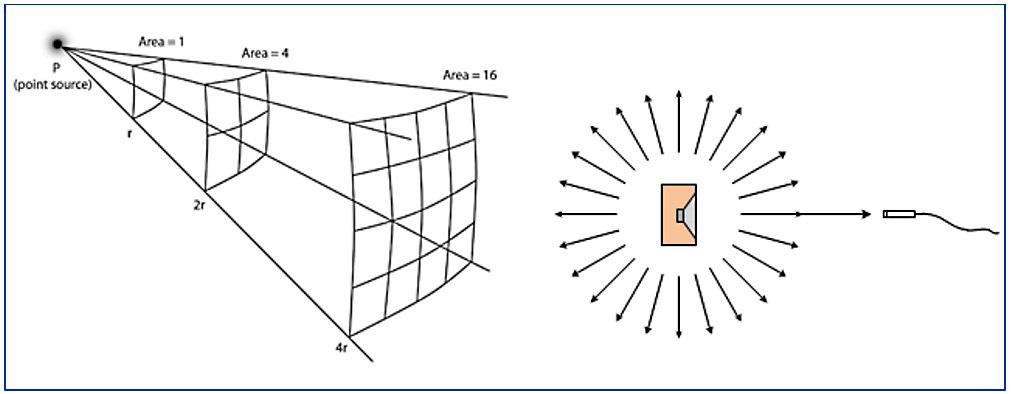
Sound intensity is proportional to sound pressure squared. Hence the sound pressure level decreases by 6 dB per doubling of the distance from the source. This phenomenon is sometime called the inverse square law or 6 dB/dd rule.
If a loudspeaker and microphone are in a free field, the mic will measure only the direct sound radiated from the loudspeaker. This is desirable – we want to measure the sound radiated from the loudspeaker itself, to have data that is representative of the loudspeaker, independent of the environment in which it is located.
If instead, the loudspeaker and microphone are located in an ordinary room, in addition to measuring the direct sound, the microphone will measure sound reflected from the floors, walls, ceiling and any large objects within the room (Figure 2). The direct sound will arrive first at the mic, followed by the first reflections from the closest surfaces and then secondary and tertiary reflections.
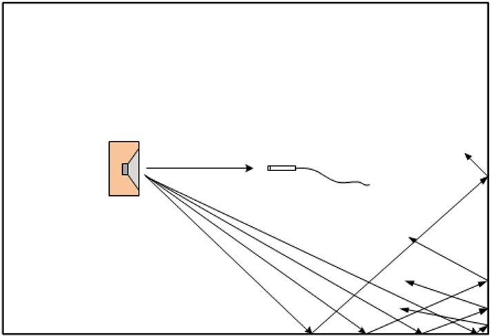
Relative to the direct sound, the reflected sound waves will be lower in level depending on the absorptive properties of the surfaces they reflect from and the path length difference. The path length differences also cause delays between the arrival of the direct sound and the reflections. These reflected sound waves contaminate the direct sound, causing an incorrect estimate of the sound radiated from the DUT and its frequency response.
An ordinary room is considered to be a semi-reverberant sound field, because surfaces in the room absorb a portion of the sound waves incident on them. The degree of absorption depends on the surface finish (for example, carpeted floor versus concrete floor) and it also varies with frequency. A fully reverberant or diffuse sound field can exist in a special room called a reverberation chamber which has walls, floor and ceiling constructed from hard surfaces designed for maximum reflections. In a diffuse sound field, sound waves are traveling randomly in all directions with equal probability.
In some cases, when testing a loudspeaker drive unit alone, measurement standards specify a half-space free field. As the name implies, in a half-space free field, the 3-dimensional space that a sound source is free to radiate into is split in half, usually by a hard, reflecting plane.
One example of a half-space free field is a sound source located outdoors on hard ground, far away from any other reflective surfaces. Another example is a hemi-anechoic chamber, in which all the room surfaces are highly absorptive except the floor, which is made of a hard, reflective material like concrete. A free field and half-space free field are sometimes referred to as a 4π (4 pi) space and a 2π (2 pi) space, respectively. This is based on the solid angle in steradians that a sound source can radiate into without obstruction.
Another important concept in acoustics is the near field and far field. Far away from a source (relative to its size), the inverse square law (or 6 dB/dd rule) mentioned above applies. At this distance the sound field has become stable and radiates from the source in a predictable way.
Close to the source, however, sound waves behave in a much more complex fashion and there is no fixed relationship between pressure and distance. In this near field, the sound level is uncertain.
Therefore, measurements should be conducted in the far field. The distance from the source to the far field depends on the size of the source. As a “rule of thumb” it is typically considered to begin at a distance of three times the largest dimension of the source [5]. However, it’s been suggested that the far field begins at three to 10 times the largest dimension of the source [6].
To achieve free field conditions, two options are available: testing outdoors or in an anechoic chamber.
Outdoors
To achieve free field conditions outdoors, a loudspeaker and microphone must be elevated high above the ground to minimize the influence of ground reflections. For example, the loudspeaker could be mounted on a tall tower, suspended from a crane, or on a boom projecting from the corner of a building’s roof. The required height depends on the size of the loudspeaker which in turn determines the required distance for the microphone to be in the far field.
Consider a bookshelf-sized loudspeaker cabinet with a largest dimension of 13 inches (0.33 meters). Using the lowest rule of thumb value for the far field distance of three times the largest dimension of the source would require the microphone to be 3.28 feet (1 meter) away from the loudspeaker.
Based on the 6 dB per doubling of distance rule, to reduce the level of reflected sound to 20 dB less than the direct sound would require a height of 16.4 feet (5 meters) above the ground. Doubling the size of this bookshelf speaker would double the height required to get the same 20 dB reduction of reflected to direct sound.
Obviously, conducting measurements with a loudspeaker and microphone located at 16 to 33 feet (5 to 10 meters) above ground is challenging! In addition to the inconvenience, inclement weather and ambient noise from wind, traffic, etc. can be problematic.
Half-space measurements can be conducted outdoors by using the ground as the reflective plane. In this case, the loudspeaker would be mounted in a baffle that is flush with the ground surface.
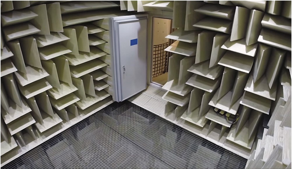
Anechoic Chambers
An anechoic chamber is a special room lined with highly absorptive material on its interior surfaces – walls, ceiling, floor and doors (such as the anechoic chamber shown at the outset of this article). To improve absorption at lower frequencies, the absorptive material (fiberglas or open cell foam) is formed into wedges, with the wedge tips facing into the room. In fully anechoic (4π) chambers, an acoustically transparent working surface above the absorptive floor wedges is usually provided by means of an open, steel wire mesh suspended from the walls.
An anechoic chamber approximates a free field above a lower limiting frequency determined mainly by the length of its absorptive wedges. This lower frequency limit can be estimated from another rule of thumb: to absorb sound of a given frequency, the significant dimension of an absorptive material must be at least 1/4 of the wavelength. Based on the 1/4-wavelength rule and the speed of sound in air at room temperature (1,129 feet per second or 344 meters per second), 3.28 feet (1 meter) long wedges can effectively absorb sound above about 86 Hz in frequency.
For practical reasons (and cost, of course), it’s rare to find an anechoic chamber with a lower limiting frequency below 60 to 80 Hz. Chambers can be calibrated to lower frequencies using a loudspeaker system with sufficient bass (e.g., a subwoofer) with known frequency response. The challenge then becomes finding the frequency response of this reference subwoofer.
It’s interesting to note that anechoic chambers are qualified in terms of how closely they adhere to the inverse square law or 6 dB/dd rule. The ISO standard covering sound power measurements in an anechoic chamber [7] specifies that measurements along traverse lines within the chamber must not deviate from the inverse square law by more than 1.0 to 1.5 dB, depending on frequency. And IEC 60268-5 [1] specifies that a chamber must be within ±10 percent of the inverse square law in the region between the loudspeaker and the microphone.
A low level of ambient noise is also desirable in an anechoic chamber, to enable measurement of low-level harmonic distortion from loudspeakers as well as the sound emitted from low-level noise sources like display screens and electronic components.
To minimize ambient noise, the best anechoic chambers are designed as an inner anechoic room inside an outer room. In addition, the inner room is often mounted on flexible vibration isolators to minimize structure-borne noise transmission from the outer room to the chamber. The chamber shown in the opening image recently set the new world record for the quietest location on earth, with an ambient noise level of -20.3 dBSPL.
Quasi-Anechoic Measurement Techniques
Due to the expense of – and limited access to – anechoic chambers, much work has been devoted to the development of “quasi-anechoic” measurement techniques which seek to enable measuring the frequency response of loudspeakers (and microphones) in an ordinary, semi-reverberant room.
These techniques are all time-selective; they work by stimulating the loudspeaker with a broadband signal and analyzing that portion of the measured response that contains the direct sound from the loudspeaker but excludes the portion containing reflections from the room surfaces.
Quasi-anechoic techniques take advantage of one of the foundations of signal processing – the equivalence of a linear system’s frequency response and its impulse response. In the frequency domain, a system’s frequency response, H(f) represents its output magnitude and phase (or real and imaginary parts) per unit input, as a function of frequency. In the time domain, its impulse response, h(t), represents the system’s output as a function of time when stimulated by a unit impulse or Dirac delta function.
These two representations of a dynamic system are equivalent, and one can be derived from the other using Fourier analysis. For example, the Fourier transform of the impulse response yields the frequency response. Similarly, the inverse Fourier transform of the frequency response yields the impulse response.
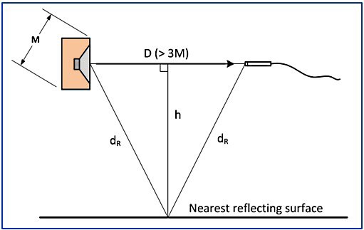
So how do time selective techniques work in practice? Consider the measurement setup depicted in Figure 3. A measurement microphone is positioned on-axis in front of a loudspeaker in a semi-reverberant room. To be in the far field of the loudspeaker, the distance d is chosen such that it is more than 3 times M, the largest significant dimension of the loudspeaker. The path length of the direct sound from the loudspeaker to the microphone is d, and the path length of the first reflection from the nearest reflecting surface (the floor in this case) is 2dR.
Based on this geometry, the time difference, T, between the direct sound arrival at the microphone and the first reflection is T=(2d_R-d)/c, where c is the speed of sound.
Figure 4 (upper graph) shows an impulse response measured 3.84 feet (1.17 meters) in front of a bookshelf speaker located 9.4 feet (2.86 meters) above the floor in a large room. The peak in the impulse response occurs at about time t = 3.5 milliseconds (ms), which corresponds to the direct path length (3.84 feet) divided by the speed of sound (334 microseconds or m/s).
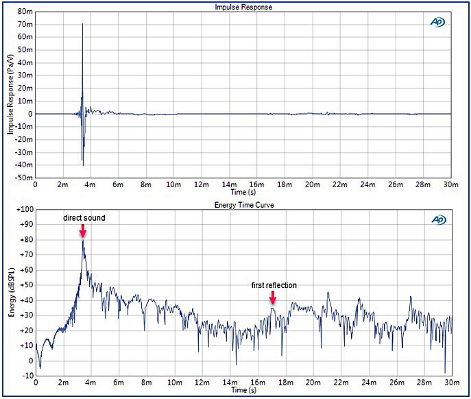
Although it’s difficult to see in the impulse response, there are small secondary peaks that occur at time t = 16.5 ms and later. These smaller peaks, which are due to the arrival of reflections from the floor, walls and other room surfaces are much easier to see in the lower graph in Figure 5, which is called the Energy Time Curve (ETC).
The ETC, which was introduced in the 1960s [9], is essentially a plot of the envelope of the impulse response. It’s plot of magnitude on a logarithmic scale makes it much easier to see the arrival time of room reflections.
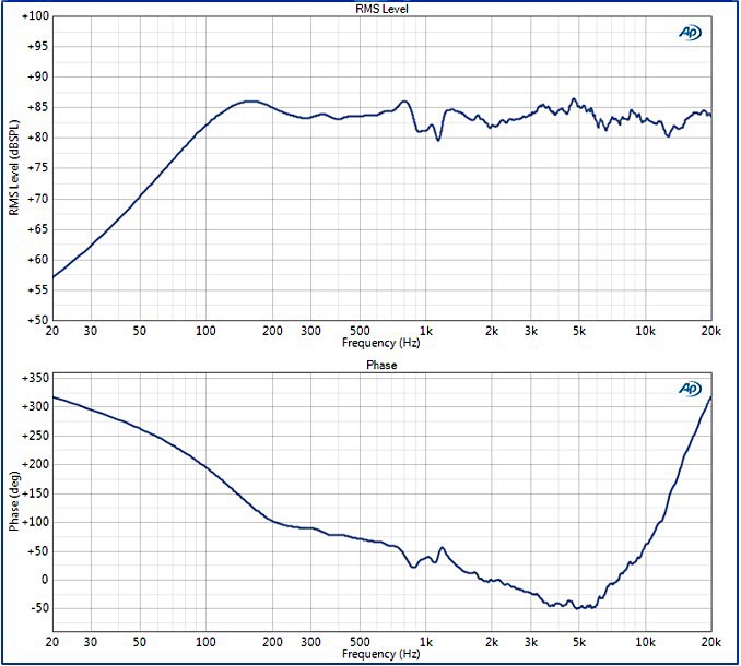
Time-selective or quasi-anechoic measurements would apply a window to the impulse response, eliminating any data after the first reflection arrives (about 15 ms, in this case), and then use a Fourier transform to compute the frequency response magnitude and phase (Figure 5). Typically, a rectangular window with cosine tapers at the beginning and end is used, to create smooth transitions. In Figure 5, the frequency response magnitude has been multiplied by the magnitude of the voltage signal applied to the loudspeaker to determine the RMS Level in dBSPL.
References
1. IEC 60268-5:2003+A1:2007 – Sound system equipment, Part 5: Loudspeakers.
2. Private communication, J. Woodgate, 2017. IEC 60268-5 Maintenance Team Project Leader for IEC TC100.
3. IEC 61305-5:2003 – Household high-fidelity audio equipment and systems – Methods of measuring and specifying the performance – Part 5: Loudspeakers.
4. Toole, Floyd (2009). Sound Reproduction: The Acoustics and Psychoacoustics of Loudspeakers and Rooms. Taylor and Francis.
5. C. Struck and S. Temme (1992). Simulated Free Field Measurements. 93rd AES Convention.
6. L.L. Beranek (1986). Acoustics. Acoustical Society of America, New York.
7. ISO 3745:2012. Acoustics – Determination of sound power levels of noise sources using sound pressure – Precision methods for anechoic and hemi-anechoic rooms.
8. J. M. BERMAN, and L. R. FINCHAM. The application of digital techniques to the measurement of loudspeakers, JAES, 25, June (1977).
9. R. C. Heyser (1971) Determination of Loudspeaker Signal Arrival Times, Parts I, II and III. JAES, vol 19.
Editor’s Note: Go here for Part 2 of this article, and here for Part 3.