Editor’s Note: This is part 1 of a 2-part series — access part 2 here.
Timecode operations are often one of the most misunderstood and frequently misused aspects of the production industry. Many in the industry itself don’t understand the subtleties involved in audio and video production using timecode operations.
Using timecode, however, is a powerful tool. While it is primarily used to synchronize audio and video together in visual media, it can provide a neat way to expand your options when, for example, using older technologies like multitrack audio tape with today’s DAW technology. In fact, this skill is a perfect harmonization of the benefits of the digital world with those that analog can provide.
The analog world provides the pleasing sonic signature of tape, while the digital recorder or DAW provides the persistent storage and editing capabilities digital technology is known for. The ability to continually record in analog, dump it into Pro Tools and then re-use the analog tape for additional tracks is powerful.
Part 2 of this series will show this handy technique to allow tracks recorded to tape to be dumped accurately into a DAW, with a focus on Pro Tools. While the concepts here can be applied to any DAW, the specifics discussed here relate to the Pro Tools hardware and software suite.
But first, part 1 – a timecode primer. What is timecode?
A Condensed History
In the days of film, sound was aligned to video by mechanical means along the edges of film. With the advent of videotape, a non-mechanical method of alignment of sound and image was needed. Enter timecode.
Timecode is a set of standards adopted by the Society of Motion Picture & Television Engineers (SMPTE) that was created to allow audio to be accurately placed with video. It’s actually a bi-phase bit stream, simply a stream of digital “1” s and “0” s whose transitions are indicated by either a single transition from low-to-high (or high to low) within a bit space to indicate a “0” or two transitions within the same bit space to indicate a “1”.
Timecode consists of 80-bit spaces in order to form the full frame. The bit sequence is organized into bit fields that can be read by a decoder. Each value in the bit field is represented by a tone. A “0” is represented by a 1.2 kHz tone while a “1” is represented by a 2.4 kHz tone. Since timecode had to travel with the medium, it was recorded (known as striping) onto an audio track of the videotape providing an instant reference on that video.
This is a good opportunity to discuss one major area of misconception within the audio world: Timecode is not wordclock and wordclock is not timecode. The misconception (and mislabeling) of timecode and its cousin wordclock is understandable; however, it is very important that we in the audio field dispel the idea that they are the same. While they both are methods of synchronization, and it is true they deal with digital bit streams, the similarity ends there.
Wordclock
When two digital devices have to exchange data, the data stream may look like that seen in Figure 1. While this data stream may make sense to the sender, the user has no frame of reference at where the data stream starts. To put this in context, imagine a comedian starting a joke with “A dog walks into a bar and sits on the first stool”.

Assuming the comedian and the intended audience understand the same language (i.e., English), we know that there will not be a problem deciphering the words spoken. If, however, the audience has no indication of where the sentence starts, the sentence could easily be interpreted as “bar and sits on the first stool a dog walks into a” or “walks into a bar and sits on the first stool a dog” or even “first stool a dog walks into a bar and sits on the”. The rules of sentence structure in the English language tell us that the period ending the previous sentence serves as the mark to know when a new sentence is beginning.
This scenario equally applies to the data stream in Figure 1. Both the sender and receiver will know the words in the language in order to make up the sentence, however in the absence of a starting point, the information received can be skewed.
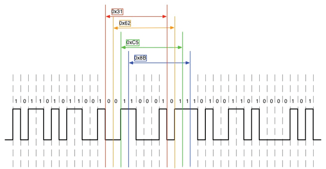
Figure 2 shows us the resulting confusion. Even though, in this case, the receiver knows this is an 8-bit system (it is supposed to read 8 bits at a time in order to form a data block), it doesn’t know where the 8-bit structure starts. So, similar to our messed-up comedy sentence, the receiver cannot understand whether the same bits indicate the data word “0x31”, “0x62”, “0xC5” or “0x8B”.
Fortunately, similar to the “period” used in English sentence structure, wordclock was devised as a method to allow the receiver to decipher the sentence being “spoken”. The wordclock is a “pulse” that allows all the members of a digital system to know where to interpret the first bit of a multi-bit word.
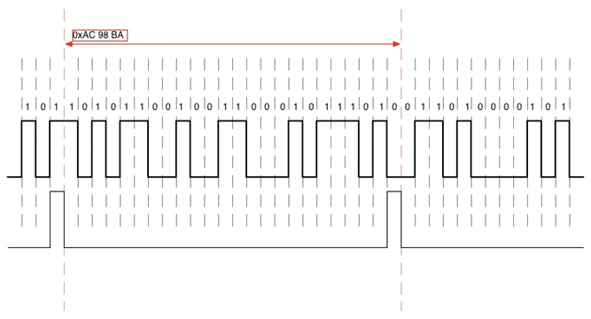
Figure 3 adds a pulse to the bit stream viewed in the earlier figures. Now that a pulse has been added, the receiver now knows exactly where the first bit resides. If this data stream were part of a 24-bit system, the receiver knows where bit “1” in the 24 bits resides. The resulting word is “0xAC 98 BA”.
Since wordclock is so important, it stands to reason that there is one and only one wordclock master in a digital system. The master generates the pulse, while all the receivers will look for an incoming pulse on its “Wordclock In” port.
As can be seen in Figure 3, the wordclock pulse only provides a timing reference. There is no differentiation between each pulse other than the fixed amount of time in between pulses. This is a significant difference between wordclock and timecode.
Timecode
As previously mentioned, timecode is similar to wordclock in that they both deal with digital bit streams, and they both have functions in synchronization. The similarities end there.
The function of timecode is to provide an exact positional reference. To draw another analogy, think of wordclock as the sound of a second hand of a clock. While you hear “tick…. tick…. tick”, and you know that a second has elapsed since the last tick, you have no idea whether the second marks “12 seconds”, “52 seconds” or “21 seconds”.
Timecode is the positional reference that, in a word, gives a “name” to that tick. Using our analogy, think of timecode as an announcer watching the clock’s second hand. With each tick, the speaker announces, “at the next tick, the time will be 36 seconds…at the next tick, the time will be 37 seconds…at the next tick, the time will be 38 seconds”. One can say wordclock marks time passing, while timecode marks the position of each moment.
Timecode comes in different variations:
• LTC (Longitudinal Timecode) – the standard audio-tone timecode.
• VITC (Vertically Integrated Timecode) – developed to overcome the issue that timecode stops when the VTR is stopped.
• MTC (MIDI Timecode) – Allows timecode information to be transferred across MIDI to allow timing of MIDI events to occur.
• MIDI Sync – synchronization of separate MIDI devices
• MMC (Midi Machine Control) – control (and some timing) information across MIDI to allow remote control of the transports and arming of various devices.
This article focuses on LTC as it is generally what is used today when one refers to “timecode.”
Similar to wordclock, there can only be one source of the timecode. All other recipients must receive and “chase” this incoming timecode. In order for this to occur, the receiver is put into a mode where its transport is disabled from user input, and it waits for timecode to appear at its timecode input port. When timecode is detected, the various bits are read until the receiver can align itself to that incoming timecode.
Once it’s aligned, the receiver starts moving its transport to the time that is read from the incoming timecode. This alignment and moving of the transport are called being “locked” to (or being “in lock with”) the incoming timecode. Timecode also has some terms that need to be defined before we attempt to use it.
Timecode Chase Modes
When chasing timecode, the user can choose between multiple styles of lock in order to determine the behavior of the chasing unit, including:
Sync Lock. Full Sync Lock is a mode where the receiver’s transport is fully locked to the movement of the incoming timecode. If the timecode stops, the receiver’s transport stops. When the sender restarts sending timecode, the receiver automatically resumes play at the time indicated within the timecode itself.
Freewheel. The world of timecode isn’t perfect. Since it was developed as an analog property, it’s subject to the issues that can have an effect on analog audio. Freewheel was developed as a methodology to provide some fault-tolerance to timecode systems. It’s defined as the amount of frames the timecode can drift before the receiver abandons chase. If the freewheel is set fairly liberally, (i.e., 10 frames or more), a badly damaged tape can still be read and chased without the transport randomly stopping and starting due to dropouts on the tape.
Chase Relock. If the incoming timecode drifts outside of the relock threshold, the chase relock determines whether the receiver will shift to the correct timecode value or if it simply continues on its current pace. It’s important to set a chase relock if your unit provides the option. If one is recording while chasing timecode, a practice that is actively done in the live broadcast, you do not want the chase relock to occur if the timecode drops out. This would cause dropouts in the recorded data, causing an issue.
Jam Sync. Another method to avoid interruptions of recorded data while chasing timecode is to use Jam Sync mode, which allows the receiver to initially wait, find and lock to an incoming timecode. However, once this lock is achieved, the receiver stops paying attention to the incoming timecode and runs its transport independent of that timecode.
Timecode Offset. This value allows the receiver to operate its transport from a spot in time numerically different than that indicated by the incoming timecode. The offset can either be positive or negative.
Timecode Frame Rates
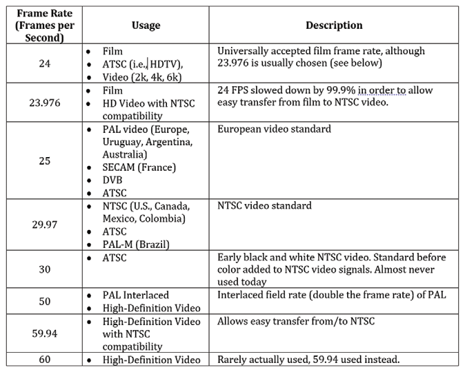
Since it began as a methodology to synchronize audio to image, timecode is dictated by a quantity called the “frame rate”. This is how many image frames are consumed in one second. The frame rate intimately relates to the actual video frame rate. Table 1 shows the common frame rates in practical usage.
As we can see, most of the timecodes frame rates are whole numbers. Some, however, are not. Isn’t it strange that a frame rate is a fractional value? There’s no physical way to have a portion of a frame, so why are there frame rates like 23.976, 29.97 or 59.94?
Previous to this point in time, the frame rate used in North America for monochrome TV was 30 FPS. This was to allow accurate timing based off of the 60 Hz AC power that was being standardized in North American power grids.
Audio was combined with the video signal by a methodology called “modulation”; when a signal is “piggybacked” onto another signal by applying a “subcarrier” frequency. In this case, the audio signal was piggybacked onto the 4.5 MHz signal within the video.
Upon the invention of color television, the NTSC (National Television System Committee) in the U.S. specified that color TV must be compatible with the existing monochrome (black and white) television specification. In order to do this, designers chose additional subcarrier frequencies within the monochrome bandwidth to carry the color components of the video. These subcarriers were “hidden” by choosing frequencies that were the same as those in monochrome but were put 90 degrees out of phase.
While this worked quite well, the only problem was that the audio subcarrier, the 4.5 MHz signal that was always there, interfered with the new subcarriers. The initial solution would have been to modify the audio subcarrier slightly, however this would affect the existing receivers. Since the mandate required existing compatibility, this was ruled out.
Instead, it was decided to reduce the color subcarrier frequencies a small amount, 0.1%. This also impacted the scan line frequency and, by extension, the frame rate by 0.1%. Changing the frame rate by 0.1% meant that instead of the rate being 30 FPS, it was now 30*(1000/1001) = 29.97 FPS.
Drop Frame Counting
While this is all well and good for solving the technical issues, the changing of the frame rate led to one “natural life” issue: 60 seconds of timecode was actually taking 63.59 seconds to elapse. An error of about 1.43 minutes would be accrued across a full day of TV programming!
This was solved by “drop frame” counting. The term drop frame doesn’t actually mean frames are dropped; it actually means that the counting of certain frames is dropped. The frames exist, it’s just the individual labels for certain frames are ignored. Think of it as a reverse “leap year” effect … in February of every fourth year, a day is added to “bump” our labeling of the passing days and months in order to align our numbering of the days with the amount of time the earth actually takes to orbit the sun.
In the case of drop frame, the counting of the 0th and 1st frames are eliminated from the first second of every minute EXCEPT for when the minute is divisible by 10. Simple, huh? An easier way to think of it is that 2 TC frame counts are dropped every minute except when that minute can be divided by 10.
An example of the way this is done is shown in Table 2. The counting, although a little odd, fixes the error incurred by the frame rate adjustment.
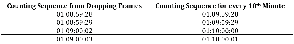
In order to differentiate drop frame from non-drop frame, a semi-colon is used between the second and the frame fields of the numeric. So, for example, 01:08:59;28 indicates drop frame is being used while 01:08:59:28 indicated non-drop frame is in use.
Conclusion
Timecode is a fascinating and effective means at synchronizing multiple devices. By using these facilities created in the early days of color television, opportunities for synchronizing previously disparate devices are opened up. Timecode is not just for video anymore!
References
1. Wikipedia entry on timecode: en.wikipedia.org/wiki/Timecode
2. Wikipedia entry on SMPTE timecode: en.wikipedia.org/wiki/SMPTE timecode
3. Introduction to the basic principles of SMPTE-EBU timecode: alpermann-velte.com/proj_e/tc_intro/tcintro.html
4. Technical introduction to timecode: poynton.com/notes/video/Timecode/
5. Philip Rees Modern Music Technology: Synchronization & Timecode: philrees.co.uk/articles/timecode.htm
6. Apple Final Cut Pro 7 User Manual, Choosing A Frame Rate: documentation.apple.com/en/finalcutpro/usermanual/index.html#chapter=D%26section=4%26tasks=true