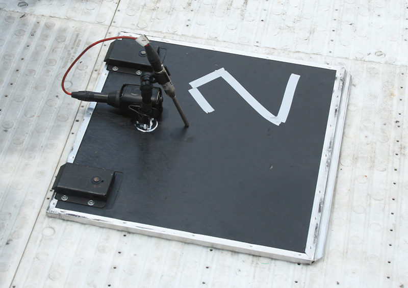
For a standard 1/2-inch measurement microphone, the center of the microphone’s diaphragm will be about 6.4 mm above the ground plane when the microphone is directly on the surface. For a loudspeaker height of 40 cm, the first notch in the comb filter would be at about 68 kHz, resulting in a level response 6 dB higher than the direct sound up to 20 kHz.
As the source height increases, the frequency of the first notch will decrease, limiting the upper frequency range of ground plane measurements to a frequency below 20 kHz. One way to mitigate this effect is to place the high-frequency driver closer to the ground (i.e., to invert a loudspeaker system with the tweeter at the top of the baffle.
As shown in Figure 6, from the perspective of the microphone, it “appears” that there is a second identical loudspeaker located symmetrically with respect to the ground plane. At frequencies below the first notch in the comb filter, the signals will be in phase and will have a combined level 6 dB higher than the level of the direct sound. This can be used to advantage by placing the microphone at a distance two times the intended measurement distance.

For example, a common specification is the frequency response measured on-axis at 1 m distance due to a sinusoidal stimulus of 1 W. Assuming the loudspeaker is small enough that 1 m is in the free field of the DUT, a ground plane measurement at 2 m will yield the same level response as a free field measurement at 1 m.
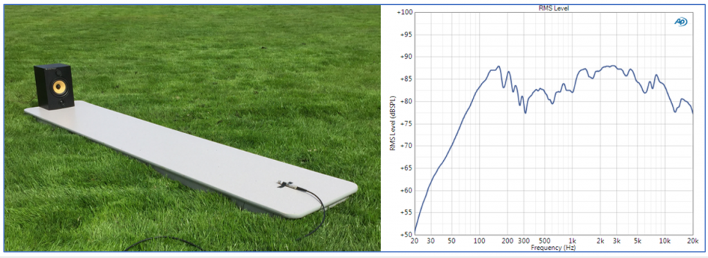
Figure 7 shows a ground plane measurement of a small bookshelf speaker in a large open field and the resulting frequency response measured at 2 m due to 1 W input. In this case, the loudspeaker and microphone were placed on a table top resting on the ground, to ensure a reflective surface.
Ground plane measurements offer an inexpensive alternative to an anechoic chamber, but they still have some issues. One issue is diffraction; due to the reflected image of the loudspeaker, the baffle appears to be twice as high as it really is, causing a different diffraction response along the edge in contact with the ground.
Also, a large open area is required with no vertical reflecting surfaces located within about 10 m of the loudspeaker. And, of course ambient outdoor noise from vehicles, machinery, aircraft and the wind is usually of concern, especially for low-frequency measurements where the output of the DUT is relatively low.
In the next part of the series, we’ll focus on the essentials of standard loudspeaker measurements.
References
- D. B. Keele Jr., Low-Frequency Loudspeaker Assessment by Near-Field Sound Pressure Measurement. JAES, vol. 22, pp. 154-162, April 1974.
- C. J. Struck and S.F. Temme, Simulated Free Field Measurements. JAES, vol. 42, No. 6, June 1994.
- Olson, H.F. Direct Radiator Loudspeaker Enclosures. JAES, 1969 Vol 17 No. 1. (reprinted from Audio Engineering, November 1951).
- Tolvan Data. The Edge. Technical Documentation, 2006 (tolvan.com).
- Gander, M. R. Ground-Plane Acoustic Measurement of Loudspeaker Systems. JAES Vol 30 No. 10, 1982.