For the past few years, give or take a pandemic or two, we in the production industry have been bombarded with tales of the “RF Apocalypse” that was coming with the conclusion of the 600 MHz spectrum auction and the subsequent re-pack of off-air TV stations and deployment of new cellular services in the recently cleared spectrum. Well, those changes have all happened, actually during the pandemic, and the question now arises: How has this affected wireless users in the content creation field (i.e., Us)?
What I’m finding is that it has affected things a lot. Has it changed “best practices” for wireless use? No, but what has changed is that now you need to know what these practices are, all of them, and use them every time you deploy wireless microphone, IEM, IFB and intercom systems.
Now you might ask, didn’t we just go through this a few years ago with the 700 MHz auction? Yes, and while that was disruptive and expensive for people who had to buy all new wireless equipment, it didn’t have as much effect on the day-to-day use of wireless in the remaining spectrum as the more recent changes.
As The World Turns
What’s different? Well, two things. First, after the 700 MHz auction, we still had 222 MHz of bandwidth to play around in (470-698 MHz, minus 6 MHz for channel 37, 608-614 MHz). Secondly, the cellular downlink services (i.e., the really strong stuff coming from the cell towers) that were deployed at that time were in the 719-756 MHz range, which left a 21 MHz gap between the highest frequency that we could use (698 MHz) and all that high energy cellular. Mind you, the uplink signal from the actual cellphones is in 698-718 MHz but those transmits are more sporadic in nature and less likely to appear on a scan as an elevated noise floor.
This time around, we are left with 138 MHz of UHF spectrum (which we also continue to share with off-air television and in some cities, public safety radios) in the UHF spectrum. And the cellular services start at 617 MHz, only 9 MHz above the highest frequency that we can use, 608 MHz (which is actually 607.900 or so). Or worse, 1 MHz above the small slice of spectrum that we can use in 614-616 MHz, if you have equipment that will tune there.
To make things even more complex, not only are the cellular frequencies closer to our operating area, spectrum wise, they are also getting physically closer hardware wise. A couple of examples:
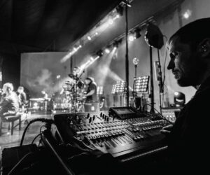
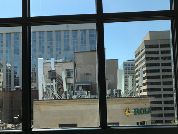
I was recently doing a site survey in a suite of conference rooms in an eight-story office building. In two of the rooms, when I got close to the windows at one end of the room, my spectrum analyzer lit up like a Christmas tree. When I looked out the window, I was looking directly at a new cell site on the roof of the three-story building across the street (Figure 1).
Similarly, my home stadium, BMO Field in Toronto, has become a cell site, with each of the four steel columns that support the roof (and stands) doing double duty as a cell tower. Sure, the antennas are facing outwards from the columns (i.e., away from the field) but it still puts a massive amount of RF energy in the air, and in close proximity to where our RF systems are deployed.
So, the reality is that now we’re much more likely to be deploying our low-power devices in a small chunk of clear spectrum (a.k.a., “white space”) surrounded on either side by high-power transmissions, either DTV or cellular. How small of a chunk? It could be as little as 6 MHz or even 2 MHz. How high power? About -60 dBm. For reference, “full bars” on a Shure Axient Digital receiver (all Rx LEDs lit) is -70 dBm.
Evolving Role
For me, as a frequency coordinator, I find that my role has evolved from being one of mostly just a person handing out frequencies to becoming more of an “RF manager” or “RF advisor” where I’m handing out frequencies and then saying “and here’s what you’re going to need to do to make that frequency work.”
And what kind of issues am I encountering?
A big one is too much gain from amplified antennas, or just too much gain, period. I’m going to go out on a limb here and say that I think the whole RF field has been living by this mantra of “must use active antennas to make up for cable losses” for way too long. I’m personally not a fan of active antennas and feel that they often cause more RF issues than they solve. I’m also of the opinion that in this era of steadily rising noise floors, cable losses are actually a good thing, as I will illustrate shortly.
RF amplifiers, either built into an antenna, or as a standalone device, cannot choose which signals they are going to amplify, so if you’re hoping they’ll boost the signal from your transmitters, they will, but they will also amplify any and all noise that’s in the pass band of your antennas. And, since that “noise” is now much closer, spectrum-wise, to the frequencies we’re using, we’re pretty much guaranteed to be amplifying it as well as our signal and consequently raising our noise floor.
An example: In 2020 I managed the 600 MHz transition at a TV studio complex on Toronto’s waterfront. This consisted of a distributed antenna system (DAS) that covered six distinct studio spaces. All cabling terminated in a central machine room where all the RF receivers (32 channels) and IFB transmitters (20 channels) were located.
As part of the update, I installed a Wisycom MAT288 eight-zone antenna distribution system. It’s a terrific device, which among other features offers both gain and attenuation (independently) for each of the 16 antenna inputs (8 x “A”, 8 x “B”). In this installation, 10 of the 12 receive antennas were Sennheiser 1031-u passive, omnidirectional types. The other two were Lectrosonics ALP620 LPDAs and the existing cable runs were all Times Microwave LMR400 (top-quality, double-shielded low-loss cable).
The shortest cable run was 125 feet and the longest 300 feet, with some intermediate runs of 200 and 225 feet. Now, you’re probably thinking: “Good thing all the antenna runs were terminating in a device with built-in gain, to make up for the losses over those long cable runs,” right?
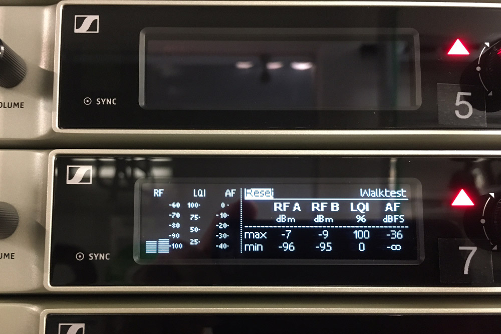
Well, in fact, I attenuated every run, even the 300-foot one, by anywhere from -8 to -12 dB. I arrived at these values by turning on one zone at a time, and then attenuating it until I was seeing no activity on the receivers’ RF displays. With this done, we walk-tested transmitters to each zone, and achieved excellent results in every space and the interstitial hallways. A few more factors to keep in mind are:
• The noise floor, which was primarily made up of at least a dozen off-air DTV signals, is essentially common to all six spaces, give or take a few dB for attenuation by interior walls etc., so it sums when all six zones (which would be the normal operating mode) are turned on.
• With the exception of one space, a large atrium, which used the LPDA antennas at one end, all of the antennas were located in the lighting grid of each studio. These were not particularly high by studio standards, somewhere in the area of 15 to 16 feet. This means that the transmitters were usually within, at most, 30 feet of the antennas, so even with the long cable runs, the signal hitting the antennas was quite strong.
• The original design had all the microphone receivers in the spectrum above 600 MHz and all the IFB transmitters in the spectrum below 600. This made for a wide gap in spectrum between the two applications. Post 600 MHz re-pack, all the mic receivers were in the 470-608 MHz range, which means they had to share spectrum with the 20 very strong transmits that the IFBs produce in the 559-596 MHz range. So, the IFB transmits were also contributing to the receiver’s noise floor.
I dealt with this issue with another Wisycom product, the “BFA” tuneable, in-line filters. These units have a number of filter modes, but the one I use most often is a 40 MHz pass band, in this case 512-552 MHz, which all 32 of the mic receivers were tuned in. The BFAs also have gain, and more importantly in my books, attenuation.
Important To Carry
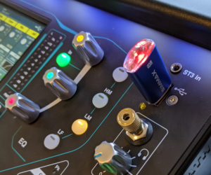
Now, not everyone needs an antenna distribution as complex as the MAT288, but one accessory that you can add to your kit for a very small investment is a set of RF attenuators. These are typically BNC-BNC “barrels” with a fixed attenuation level. I carry at least a pair of -3 dBm, -4 dBm and -6 dBm attenuators with me on every gig.
A practical example of using attenuators to improve your noise floor: We’re allowed (by the regulatory bodies, FCC in the U.S., ISED in Canada) to operate wireless systems in occupied DTV channels that measure -84.00 dBm and below. That’s -14 dBm below the -70 dBm example I gave earlier as “full bars” on a popular wireless system.
By inserting a pair of -6 dBm attenuators on the A & B and antenna inputs, you’ve just knocked the noise floor down to a respectable -90 dBm. Does the RX signal get attenuated by the same amount? Yes, it does, but typically, transmitters are putting out more signal, a lot more, than what’s required to hit full bars on the receiver, so in this case, the signal-to-noise ratio has been effectively improved by reducing the noise floor by -6 dB. In effect, what we need to do now is make a distinction between the noise floor, off air, and the noise floor in the receivers.
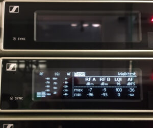
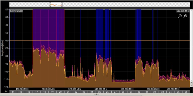
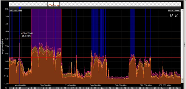
Figure 2 and Figure 3 show the difference between an active LPDA antenna with 3 dB of gain, a passive LPDA, and the latter with a -3 dB pad. Staying on the subject of filters, I highly recommend adding at least a pair of filters to your kit.
There are a number of approaches you can take to filtering, starting with the broad strokes of using a 470-616 MHz bandpass filter such as the ones from Professional Wireless Systems (PWS). These will attenuate such out-of-band signals as Land Mobile Radio (LMR, a.k.a., “walkie-talkies”) on the low side (below 470 MHz) and the cellular downlink blocks on the high side (above 617 MHz). Alternately, one can go for a more focused approach by using model/band specific filters like the ones RF Venue offers or go with filtered antennas such as the ALP690 from Lectrosonics or the LFA from Wisycom.
Regarding antennas, I’ve mentioned this before but it bears repeating: LPDA (paddle) antennas and helical types are both directional antennas, with receive patterns that are roughly equivalent to cardioid microphones. This means that it very much matters where you point them to maximize their pick-up of the desired signals (both RX and TX). It also means that, because they have nulls, again like a cardioid microphone, it matters what you point them away from. Put another way, careful aiming of directional antennas can both maximize reception and minimize the pick-up of unwanted signals.
Going Beyond
Another aspect of this is that we now need to get our heads up and look beyond the stage to see what else our antennas may be pointing at. An example of this is setting up on a festival stage – what do you see when you look off stage in the direction that your antennas are pointing? If you see a cell tower a few hundred feet away, you might want to consider relocating the antennas so they’re off-axis to the cell tower instead of pointing directly at it.
System prep is another area where the RF game has changed. I’ve found that many PA companies have excellent systems for getting loudspeakers, consoles and associated hardware out the door but lack the tools to properly verify their wireless systems.
When prepping an RF system, it’s important that every cable, adapter, and accessory, from the antennas to the rack (and from the rack to the antennas for TX’s) is tested and working properly. This requires specialized test equipment that measures performance at RF frequencies.
With the possible exception of identifying cables with outright breaks in them, ordinary DC cable testers like those we use for microphone and loudspeaker cables are not the right tool for RF cables. The test “frequency” of a DC cable checker is 0 Hz, but for argument’s sake let’s call it 1 Hz and then realize that the frequencies we’re interested in are six-hundred-million times higher. How those cables (and adapters) perform at those frequencies is a very different test than just passing a DC current and turning on an LED.
I will deal with what equipment and procedures are best suited to the prep and quality control of RF gear for events in a future article, but in the meantime, increasing awareness of worn, crushed, bent and otherwise damaged cables, connectors and hardware and not using them provides a good start in increasing the performance and reliability of RF systems.
And finally, something that will go a long way in easing the pain of working in the reduced RF spectrum that we’ve been left with is the idea of being a good RF citizen. What does that mean? It means using the spectrum responsibly and with the idea that you are of necessity, sharing it with others. In practical terms, it means:
• Use only as much transmit power as you need to do your event. It means starting at a low or “normal” setting and only reaching for the “high power” setting when you’ve exhausted all other avenues.
• Get in the habit of using “non-transmit” modes when powering up RF gear. All professional IEM and IFB systems have these modes, as do many microphone systems.
• If you’re at an event with a frequency coordinator, that person should be giving you a list of your frequencies either before or while you’re setting up. Making sure you’re tuned to those frequencies before lighting up will go a long way towards cutting down on “rogue” frequencies popping up during other acts – and yours when others extend to you the same courtesy.
Note: The author would like to thank the folks at the Solotech Toronto shop for making a Shure Axient Digital system available to produce some of the illustrations for this article.